
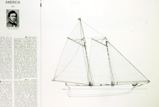
Here we have a project to design the frames for the famous schooner America, the famous ship that started one of the longest-running athletic competitions in the world, the chase for America’s Cup.
America was originally built as a yacht to showcase American yacht-building skill and to make a little money by winning yacht-racing competitions. She was a real racer/cruiser.
There is an excellent description of the history and career of America on the Wikipedia page for the schooner: Wikipedia – Schooner America
Here are a few details or the original yacht:
- LOA: 101′ 3”
- LWL: 89’ 10″
- Beam: 22′ 10″
- Draft: 10’ 11”
- Designers: James Rich Steers and George Steers
- Year Designed: 1850
- Builder: George Steers and Co. Long Island, New York
- Launched: 1851
- Scrapped and burned in a shed in 1945, Annapolis, Maryland
Scale model dimensions, at 1:20 scale:
- LOA: 60.75”
- Beam: 13.7″
- Draft: 8.3” (including 1.75″ allowance for stability)
Next is to establish the actual design criteria:
Standard Equipment:
- Topsides identical to the drawing.
- 10% more volume below the waterline.
- Two thicknesses for the keel to aid in keeping the hull straight during planking.
- .0625“ offset for hull planking
- Bulkheads are 1/8” birch plywood.
Starting Point – The Original Plan Sheets
| Here we have a look at the starting point of the design. These pictures are from the book of America’s Cup yacht design and are missing a lot of detail. This is an interesting project in particular because there is so little accurate information about the original construction. Much has to be inferred from pictures and old paintings. | |
 |
 |
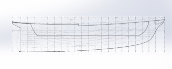
Modifying the Underwater Shape
| The drawings were then chopped up so the area below the waterline could be tweaked for R/C modelling. The drawings are inserted into Solidworks on separate planes so they can be stretched separately. As noted in the builder’s requests the keel was lowered by about 1.75″. When the frames are sketched, the discontinuity will be smoothed with a long spline.
Have a look at our page on the design and fabrication of Malabar, by clicking here. The adjustment of the shape of the hull and the insertion of the sketches into Solidworks is done in a similar manner in most models. |
Building up the design in Solidworks
| The drawings are inserted in the software and stretched to fit the requested dimensions. For these projects, where all parts are intimately connected, we use Multi-Body parts in Solidworks. | |||
 |
Here the main dimension outline and station positions have been prepared and the keel has been drawn and extruded. | ||
 |
America has an interesting arrangement for the sheer plank. It was a challenge to figure out how this would have been created on the original ship, especially around the stern, where the cap rail wraps around quite pleasantly. | ||
 |
I was expecting the sheer plank and the deck to line up but I haven’t found information that shows this, one way or the other. I opted for one line for the sheer and another for the level of the deck. | ||
 |
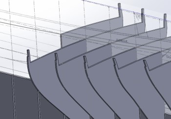
Once the various 3D curves are created, using the Projection tool in Solidworks, the bulkhead shapes are attached to those so that everything can be tweaked if needed. | ||
 |
Next, the tops of the bulkheads are added. These are used so the model can be built easily on a table. This is quite useful for large models. | ||
 |
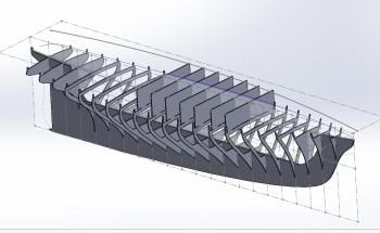
Next, the T-rail parts are added and the 3D Multi-Body is ready to be disassembled and inserted in the 2D for cutting. | ||
 |
Finally, For this model, a simple 2D exploded view is created and inserted in a 2D drawing. Making the assembly drawings is my favorite part of Solidworks projects. | ||
Assembling the Frames
| The builder has been gracious enough to send me pictures of the model from the moment he started assembling the frames. I find Solidworks is the right software for doing these frame sets. This sets was designed in Solidworks, cut, and shipped direct to the client. The parts were tested in the software. There was no prototype. Sure, there are some areas that need to be addressed but we knew about them even before cutting. | |
 |
 |
Dealing with the Transom
| The various drawings and photographs show conflicting designs for the transom. After some fiddling and decision-making, the builder himself created this lovely transom. This is one of the great parts of working directly with a builder on a project; each detail can become unique right from the start. | |
|
|
|
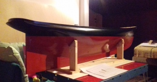
Choices, choices!
| I don’t think I’ve ever seen quite such a lovely planking and finishing job on a model! And yet, the Italian builder, like so many most excellent Italian artists, was not happy with the finish and then painted the model to even higher standards. I am really happy to have had the pleasure to participate in the construction of such a great model. | |
 |
 |
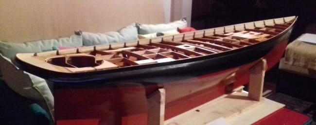
Internal Structure
| A picture really is worth a thousand words. Several things can be seen in this picture. You can see the nice deck camber that was designed into the frames. You can see the step from the stern deck to the main deck. You can see the nice gently reduction of the bulwark from bow to stern, and you can see the extra bracing the builder has incorporated for the various lines and controls. A masterful job. | |
 |
|