
This design was started on June 11th, 2020.
The design is created in Solidworks, using Multi-body, and sheet-metal features. If you are interested in the subtleties of the design, please contact me through the contact page on the site.
Actual boat:
LOA: 74’
LWL: 72’
Beam: 14’ 6”
Draft: 4’
Year Designed: 1936
Builder: Purdy Boat Company, Port Washington
Designer: Ned and Gil Purdy
Launched: 1937
Displacement: 25 tons
Engines: 2 x Caterpillar C-18 1,000 hp. Each, running at 2200 RPM
Cruising speed: 36.5 knts
Engine thrust: 6,000 lbs
Propellers: 27 x 29 Nibral 4-blade – Michigan Propellers
Rebuilt completely in 2005 at Brooklin Boatyard, Maine
Scale model dimensions, at 1/12 scale
LOA: 74”
LWL: 72”
Beam: 14.5”
Draft: 4”
Model design criteria:
The model is designed to ease construction. Using multiple frames, and many bulkheads and supports means a builder has plenty of material to work with in case they want to make modifications to the design, based on their methods, complementary parts, or interested.
o between 38 and 42 frames.
o Four keels of 1/8” each This gives the total width of the keel at ½”.
o 3/16th offset for hull planking
o Inside keel to support rabbet plank.
o Bulkheads are 1/8” birch plywood.
o Complete set of deck structures and some furniture.
The Outline
| The outlines of the boat give her the iconic character that has kept her relevant all these decades. I spend a long time on getting the various outlines just right. | |||
 |
Line drawings are inserted on planes set up specifically for the pictures. | ||
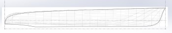 |
My first attempt at getting the side shape right. Note that my original line followed the outside edge of the line drawing. That just didn’t look right. | ||
 |
I found a very faint drawing that had the words “Brooklin” in the corner. This drawing seemed to have more swoop in the transom. I like this shape. | ||
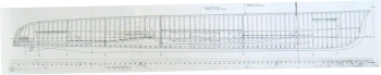 |
A client in Norway sent me this drawing that had been published on the Brooklin Boatyards website a few years ago. | ||
Keel and Sheer
| Here are the lines superimposed over the four different drawings that I worked with. The final lines are an average of the various line drawings. | |
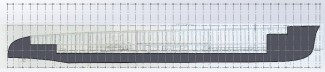 Fig.1 – Keel-Cut-1 Fig.1 – Keel-Cut-1 |
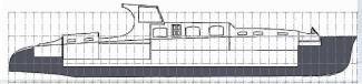 Fig.2 – Keel-Cut-2 Fig.2 – Keel-Cut-2 |
 Fig.3 – Keel-Cut-3 Fig.3 – Keel-Cut-3 |
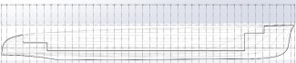 Fig.3 – Keel-Cut-4 Fig.3 – Keel-Cut-4 |
Next, Developing the Frames
| Frames and other lines are made with splines, using the smallest number of nodes possible. | |||
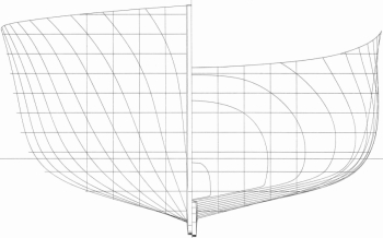 |
The best lines I could find. They only cover half the frames needed, but the intermediate lines will be drawn by hand. | ||
 |
What makes a boat are the sheer, deck line, and shape of the keel. This is where I spend many hours making sure I have a pleasing shape, that reflects accurately a boat’s character. | ||
 |
The first few frames started. | ||
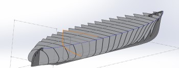 |
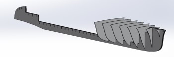
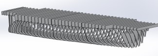
The original number of frames is covered. Next is to add the intermediate frames to make this look more like the real boat. | ||
 |
All intermediate frames included and opened up. | ||
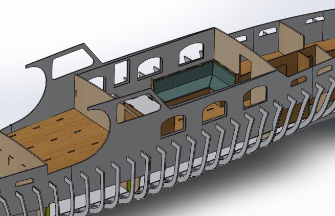
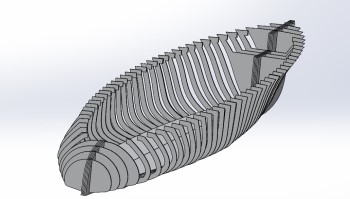 |
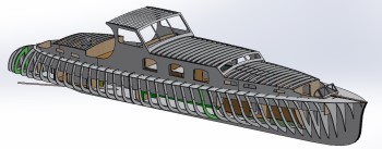
The hull is completed. The bulkheads have been opened up, a lower deck has been installed, and the frames are ready for the cabin structure. | ||
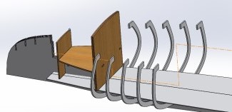
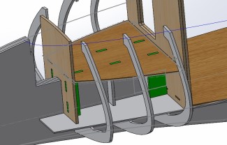
The Cabin Structure
| The cabin structure is designed as a separate entity that can be dropped into the hull as one section. The thinnest material was used wherever possible. This is so the bulkheads look to scale as much as possible but also to keep the weight of the model as low as possible. | |
 |
 |
 |
 |
 |
 |
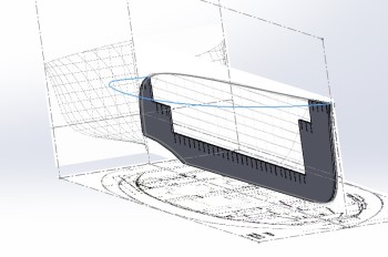
The Large Side Panels and the Cabin Roofs
The picture below shows all the cabin pieces. What is left at this stage is to inert the long, curved, cabin sides.
 |
|
|
The cabin sides are created using the Sheet Metal features of Solidworks, using large radii arcs and “normal to” cuts for the windows. Using the Sheet Metal features means the laser-cut sides will fit fairly exactly. |
|
 |
|
|
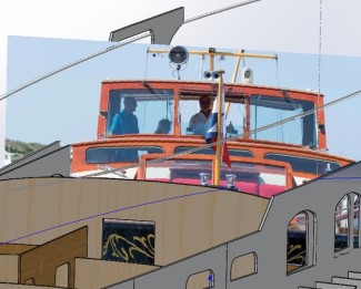
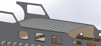
With the sides done, it is time to direct our focus on the roofs of the cabins and the flying bridge. These curves also need considerable thought as they are part of the character of the boat. These are not simple curves, as one would expect, but a combination of curves in three dimensions. In fact, no two beams are identical.
|
|
 |
 |
 |
 |
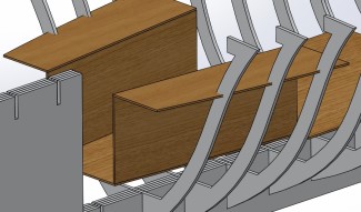
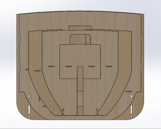
A Few Extra Details
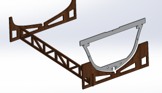
| A few extra details are added to aid in the construction and complete the design. For example, a proper king-plank was designed for the bow and some conduits were created in the frames, some in the sides potentially to be used for wiring and some under the lower floorboards, to imitate limber holes in the real boat. | |
 |
 |
 |
 |
Overall Views of the Parts
| There are over 250 laser-cut parts in the design. The complete package of parts weighs close to fifty pounds but can be divided into the parts for the hull and the parts for the cabins. | |||
 |
This image shows all the parts that are laser-cut. Material for windows is also included. | ||
 |
Here is a view of the parts, with the T-rail sections removed. This gives a good idea of the overall look of the model. | ||
Assembly Progress
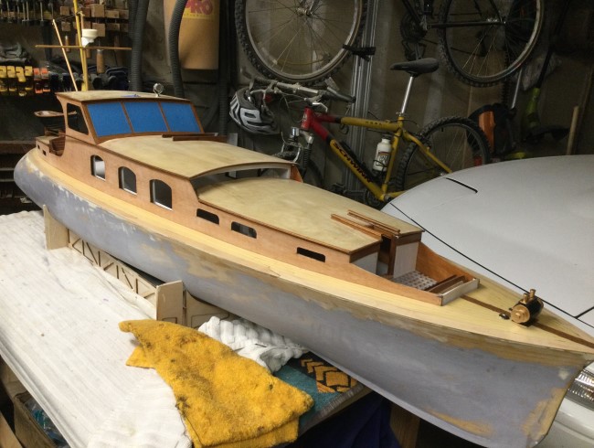
The first kits were sent out in January 2021.
|
In June 2021, the first model is at this level. At 74-inches overall, she is quite a model! |
|
 |
|
|
This is a great challenge for a seasoned builder. Because of the amount of material and parts, there is plenty of room to modify the design to suit a builders needs, interests, and skills. For more information on the construction, please check out the construction details page for this model. Thanks for looking! |
|