
Design completed in February, 2020
Here is the beginning of a interesting design project; a 1/3 scale construction of the George Crouch design Miss Massachusetts.
I create my designs in Solidworks and then cut the patterns on a 24″ x 12″ laser cutter. I hope you like this new design.
Designer: George Crouch
George F. Crouch (1879–1959) was an American boat designer. He worked for the Dodge Boat Works in Newport News. Three speedboats built to his designs won the first three places in the 1924 Gold Cup of the American Power Boat Association.
When stepped hydroplane boats came into prominence in 1927, he designed Miss Massachusetts, an 18’ 151-class hydroplane for Llewellyn T. Savage, New England distributor for Dodge Watercraft.
The boat was built by at the George Lawley & Son shipyard in Neponset, near Boston. She was powered with a 151-class, supercharged inline four-cylinder Miller racing engine.
LOA – 18’
Beam – 5’
Scale model dimensions and details:
Scale – 1:3
Length – 72”
Beam – 20”
Number of frames – 10 x 2 frames of 1/8” each. This will allow for a more realistic look to the frames.
Frame offset – 1/8″ all around for planking and deck.
Keel – four thicknesses of 1/8”. The two inside strips will be opened out to allow for the propeller tube.
There is potential for creating some sides for the cockpit and possibly some stringers but that will be decided once the 3D is started.
Here we go!
Collecting Information
| I had very little to go on to start this project. The lines I received did not have frame positions and had not been completed. I did find a picture on the internet that might help and a couple of pages from an old boating magazine.
From this first picture, and the fact this is going to be a large-scale model, I decided I was going to use four 1/8″ thicknesses for the keel and two 1/8″ thicknesses for each of the ten frames I am going to design. Because I decided to use four thicknesses for the keel, I will use two of them to make a space for the propeller shaft. |
|||
 |
I really thought this boat was a lot bigger. It never occurred to me that people zoomed around in such small craft but, hey, to each his own! | ||
 |
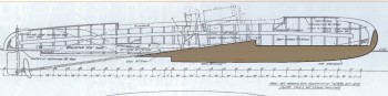
Part of the drawing I received as a starting point for the model. I sure had a hard time figuring out what was going on here. | ||
 |
Stern view that was included in the drawing. | ||
 |
There were no stations placed in the drawing so I was going to have to infer the shape from the picture above and those station lines. | ||
 |
I eventually found these couple of pages from an old magazine, describing fairly clearly what these boats were, when they were designed, why, and by whom. That’s a picture of George Crouch lying on the deck of one of his bigger designs. | ||
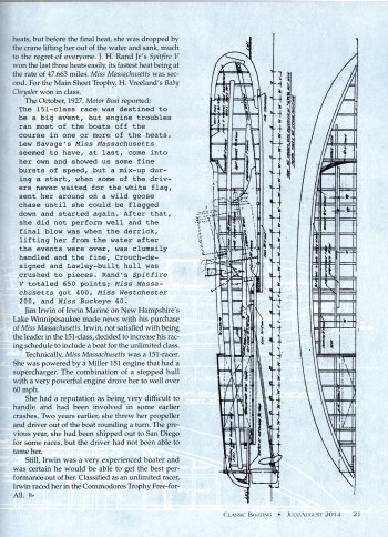 |
Finally, here’s a picture, and some good descriptions, about how these boats were built. This picture gave me a good idea of how to place the stations on the model. | ||
Inserting the .dxf files into Solidworks
| First tests are successful. The .dxf file opens nicely and I can select the lines I need clearly. The connection between all the parts will be the waterline. I will actually draw the waterline right into the laser-cut parts at the end.
Descriptions of these quite positive and encouraging first steps are outlined with the pictures. It sure would be nice to get this project completed in days instead of weeks! |
|||
 |
I pulled out this picture and will use it to set the station planes. | ||
 |
This picture shows the central keel piece, showing the propeller allowance. | ||
 |
This picture shows the planes that will be used to create the bulkheads. | ||
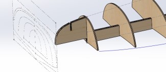
Building up the 3D Model
| Surprisingly, I was able to wrestle this project into submission more quickly than I had anticipated.Here’s how it went:
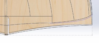
As I like to work in Solidworks and like to get feedback from builders and designers, I include a few specifics about my design methods. Figure 1 shows how the splines are created. I use as few spline points as possible. Happily, in this case, I was able to use just start and end points for the curves. With few points you get nice shapes. As soon as you add even one point along a spline, you create a potential inflection point that then becomes a bump in the surface. The “Pierce” function is very nice because it forces the corners onto points in a plane. Note the 1/8″ offset all the way around the bulkhead. This is to take into account the thickness of the planking. Figure 2 shows a view of the frames from above. As you can see, the edges of the frames seem to be inside the outline of the boat. This is normal since the frames have been reduced by 1/8″ all around. After faring and planking, the hull should work its way to the outer line. Figure 3: I sure would like to learn how to use surfaces in Solidworks in order to make it easier to create the perfect frame. In this case, the profile is done by eye. Figure 4: Using the transparent button allows you to see some of these curves easily when you are working. Figure 5: Figure 6: Figure 7: Finally, the hull is created and we get to the construction of the T-rail. This was an interesting project because the hull is basically an upside-down half-barrel. Typically, these boats are build upside-down. This means I can stretch the T-rails quite far across underneath the hull, in order to make the structure more stable. I also try and keep the T-rail as close to the frame as possible in order to save on wood at cutting. In this case, it occurred to me that it would be difficult to reach in-between the T-rail and the hull so I reduced the width of the “ears” on the T-rail and also reduced the width of the tabs. Of course, since each frame is a double-thickness baltic-birch frame, it will still be solid as a rock during assembly. But, hopefully, I’ve given enough space that the builder will get most of the planking done with the boat on the frames. Figure 8: Once that is all done, off we go to the creation of the 2D. Always force your 2D to 1:1 scale from the beginning. Do not count on your software to do the conversion for you. It would be a shame to create a nice model and end up with a 3″ boat instead of 72″! |
|
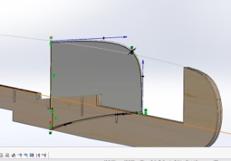 Figure 1 – Splines Figure 1 – Splines |
 Figure 2 – First Frames Figure 2 – First Frames |
 |
 |
 |
 |
 |
 |
Construction
Construction photos will be added as they are received from the builder.
← Back