
May, 13th, 2020
Here is another build for an avid J-class racer, Spinnaker225, whose work can be found on www.rcgroups.com . This particular build has its own build that can be found here.
The design will be created in Solidworks and cut on a laser-cutter, in 1/8-inch Canadian birch plywood.
As with previous designs for this builder, he sent me a scan of a page from the big book of America’s Cup yacht designs. It was pretty straightforward to use the excellent scans.
Once he received the parts, I was most interested to see that the builder decided to create a working centerboard for the model. I will have to consider this right from the beginning if I have a chance to build another J with a centerboard.
So, let’s get to the design!
Here is the starting point:
FROM THE J-CLASS WEBSITE:
• Research on dimensions of actual boat and conversion to 1/16 scale
o 120 feet, 9 inches
o 80 feet at the waterline
o 23 feet at the beam
o 14 feet 6 inches of draught
o 128 tons
• This converts to:
o 90.5625 inches
o 60 inches at the waterline
o 16.58 inches at the beam
o 10.875 inches of draught
o 62.5 pounds total scale weight
Building up the Solidworks model
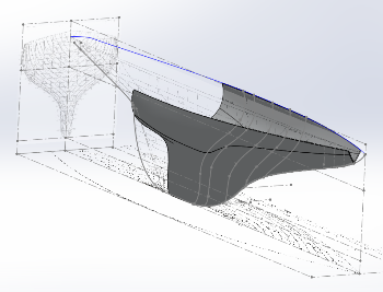
I inserted the drawings on three perpendicular planes away from the drawing area. Be careful not to use the same sketch plane for the pictures as for the extrusions. That’s an recipe for dragging the pictures around by mistake.
I made an attempt to draw the 3D shape first but the basic surface features cracked up at the stern edge of the keel. I will need to improve my skills with the surface features of Solidworks.
Everything else went smoothly and I cut the parts and shipped them to the builder.
 |
One of my first attempts at using the Surface features in Solidworks to build up the model. Lofting on these complex shapes cracks up around the keel area. I need to upgrade my skills. | ||
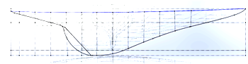 |
I spend the most time on the keel profile. These boats are somewhat similar so making sure I can reproduce the slight differences is important. | ||
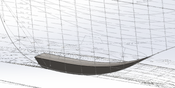 |
The extension on the keel. The AMYA class rules allow a two-inch extension to the keel. | ||
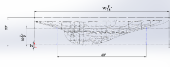 |
Basic dimensions are set and sent for approval. |
The Assembly
One should not be daunted by the difficult or complexity of building these models. Sure, they are big but that doesn’t mean they are difficult to build. It’s actually easier to work on a large object than a small one and there is a wealth of information available to help a builder work their way through such a model. We have plenty of resources that we can pass along to anyone who wants to build one of these most-excellent models.
Below are a few pictures taken from the build long mentioned above.
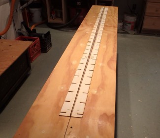 Figure 1 – T-rail base |
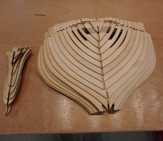 Figure 2 – Bulkheads ready to install |
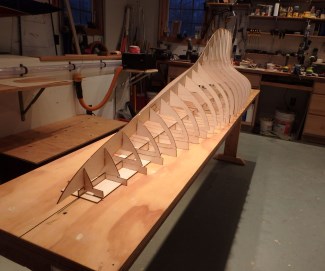 Figure 3 – Bulkheads in place |
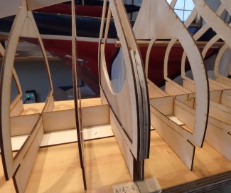 Figure 4 – Mast support |
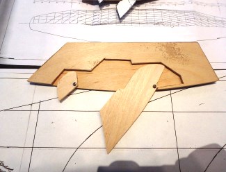 Figure 5 – Centerboard well |
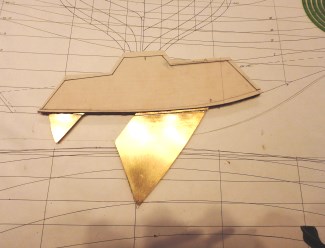 Figure 6 – Brass boards |
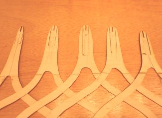 Figure 7 – Adjustments in the bulkheads |
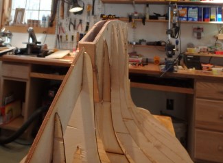 Figure 8 – Centerboard box installed |
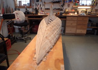 Figure 9 – Planking in progress |
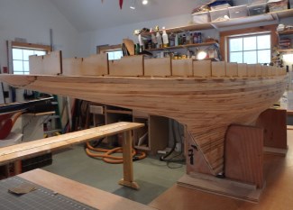 Figure 10 – Out of the build board |