Hello Everyone and welcome to a new build. After the design of the 12-meter Liberty, I am starting the design of a new boat for Spinnaker225, whose work can be found on www.rcgroups.com .
This is going to be interesting as this design is a team effort. Generally, I do all the design work based on ideas that are discussed with a builder. In this case, the builder has done much of the development work himself and has asked me to build the 3D model, and cut the parts, based on his design. We hope that this will reduce the total amount of time I have to spend in CAD.
As a Solidworks user, this is interesting because, as the builder works in Autocad, it allows me to mix different types of software to arrive at an accurate end result.
Three things concern me even before starting. Hopefully, these issues will be easy to handle.
First, I am concerned that the files I receive with .dxf extensions do not open at precise locations in a Solidworks part file and none of the lines are fixed with reference to an origin. I will have to think of a strategy to fix the appropriate lines in space and also fix the parts with respect to one another. More on that later, as we get into the project.
Second, I am concerned that the .dxf files do not support splines easily. This means I will open files as combinations of lines and arcs, instead of splines. Are the parts going to be smooth? Will this slow down the laser? Will the part files, when converted to Solidworks, be large? We will see.
Finally, I am concerned that the arcs and lines are not guaranteed to be tangent to each other throughout the parts. Depending on the number of lines in each part, this may, or may not be, an issue. Again, we will see.
So, let’s get to the design!
Here is the starting point:
FROM THE J-CLASS WEBSITE:
“J8 is an unbuilt 1935 Frank C Paine A design. Frank Paine had previously designed the yacht “Yankee”, which was built by Lawleys in 1930. She is the longest waterline J Class designed, with the highest keel aspect ratio, combined with the lowest wetted surface area. Frank Paine had already calculated in the 1930s that it was better to take a penalty on an increased waterline length in a trade off against sail area and displacement.
CURRENT MODERN TOPAZ SPECIFICATION
LOA: 42.7 m (140’)
BEAM: 6.75 m (22’2”)
DRAUGHT: 4.72 m (15’ 6”)
WEIGHT: 175.0
MANUFACTURER: Holland Jachtbouw. Hull built by F. Bloemsma Aluminiumbouw
CONSTRUCTION: Aluminium”
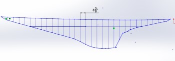
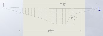
Scale model dimensions ; scale is 1 :16
LOA: 103’ 1/16”
LWL: 68”
Beam: 16 5/8”
Draft: 13 7/16” (actual would be 11 5/8”), with the inclusion of a 2″ allowance for the J-Class.
Inserting the .dxf files into Solidworks
| First tests are successful. The .dxf file opens nicely and I can select the lines I need clearly. The connection between all the parts will be the waterline. I will actually draw the waterline right into the laser-cut parts at the end.
Descriptions of these quite positive and encouraging first steps are outlined with the pictures. It sure would be nice to get this project completed in days instead of weeks! |
|||
 |
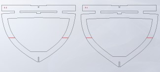
Here is a section of the .dxf file. The original Autocad file has all the parts on one space, which is perfectly normal. I will import the whole file into Solidworks for each part and select what I need. | ||
 |
Here I have highlighted one line. As can be seen, the line is made up of several arcs and lines, not one or two splines. Since we are aiming to reduce CAD time, I will not convert these to splines in Solidworks. | ||
 |
Once in Solidworks, one can see that the lines are all blue. This means nothing is constrained and one must take great care to fix the appropriate lines in space in order for Solidworks to create a solid. | ||
 |
Once constrained, it is important to make a quick drawing and verify the general dimensions. | ||
Building up the 3D Model
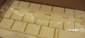
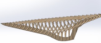
| This method is working out nicely so far. Fig. 5 is a picture of a few bulkheads inserted at the correct spots. Fig. 6 shows the offsets, Fig. 7 shows the cut-outs, and Fig. 8 shows the keel reduction.I found just one issue in the transition between file types. Because the original parts are not aligned in any way with an origin, I had to create planes for each of the bulkheads that I could then use to make the relationships in the main assembly. That should work easily but it’s not always obvious that all the planes are perfectly perpendicular to each other. One should be aware of when creating planes on parts. | |
 |
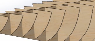 Fig.6 – Offsets can be seen Fig.6 – Offsets can be seen |
 |
 |
Keel and Bulkhead Detail
T-rail, Drawings, and Parts
ConstructionConstruction photos will be added as they are received from the builder. |
|||||||||||||||||||||||||||
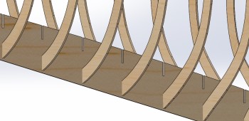
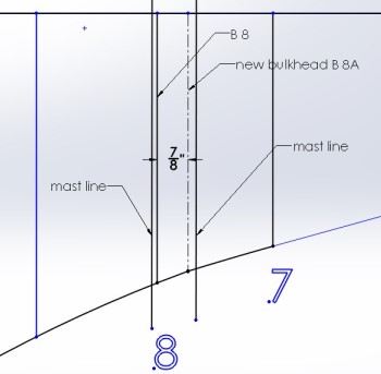
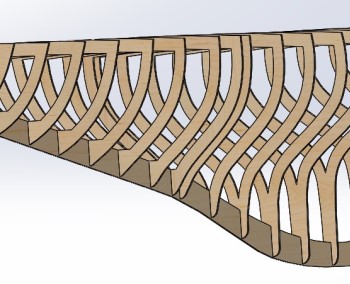

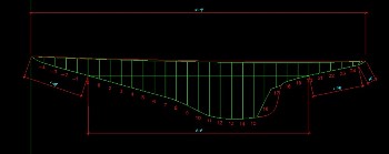
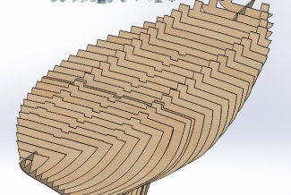 Fig.11 – Shaft angle on drawing
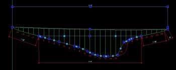
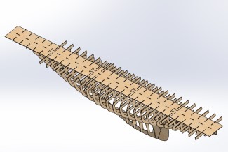 Fig.12 – Rudder end options