
Greetings!
I usually design scale models in Solidworks for large scale R/C sailors but a builder called me and asked if I could design a boat for his N-scale train layout.
His layout represents a port “somewhere in Northern Europe” so we thought a “Dunkirkmax” dimension ship would be in order. However, there is a restriction in the layout itself and I was requested to remain within 1400mm for the maximum length of the vessel.
The builder suggested we redesign the Royal Accord bulk carrier to fit within his requested dimensions.
He found some interesting plans of a model in 1/200 scale and, with a bit of research done on the ship itself, and with some ideas in mind, we were ready to start. Please note that this is a private construction and I do not have the copyright to the plans. This means I will not be publishing them here. If you want the plans, please contact me through the Contact Page of the website and I will get you in touch with the builder, who will let you know where he got them.
First, some basics about Royal Accord:
Call Sign: 3EUA9
Length Overall x Breadth Extreme: 288.93 x 45 m
IMO number 9393187
MMSI 370064000
Name of the ship ROYAL ACCORD
Former names ROYAL ACCORL (2018, Panama) ROYAL ACOORD (2018, Panama)
ROYAL (2018, Panama) ROYAL ACCOBD (2017, Panama)
ROYAL H4 (2017, Panama)
Vessel type Bulk carrier
Operating status Active
Flag Panama
Gross tonnage 90111 tons
Deadweight 180129 tons
Builder SAIJO DOCKYARD – SAIJO, JAPAN
Classification society NIPPON KAIJI KYOKAI (NKK)
Owner TOKEI KAIUN – IMABARI, JAPAN
Manager TOKEI KAIUN – IMABARI, JAPAN
Description ROYAL ACCORD is a Bulk carrier built in 2009 by SAIJO DOCKYARD – SAIJO, JAPAN. Currently sailing under the flag of Panama. Formerly also known as ROYAL ACCORL, ROYAL ACOORD, ROYAL, ROYAL ACCOBD, ROYAL H4. It’s gross tonnage is 90111 tons.
General dimensions of the model:
The actual length of 288.93m, or 947.9’ (947’ 11”) translates to 5.9246’ at 1/160 scale, or 1.80m.
Required length of the model is a maximum of 1.4m.
The beam of 45 meters translates to 147.638’ or 11 1/16” at 1/160 scale, or 28.125 cm.
Considering the restrictions of the space requirements of the model, the beam will be drawn at 28.125cm, the bow and stern will be shaped accordingly, with the castle also drawn to correct scale. The center sections, however, will be adjusted to fit a bulk carrier of approximately, and at most, 224m.
Starting Point – The Original Plan Sheets
Here we have a look at the starting point of the design. These are the two plan sheets that we started from. There are no line drawings and no dimensions so the information is quite sparse. The design begins!
 Fig.1 – Page 1 of 2 Fig.1 – Page 1 of 2 |
 |
Next, designing in Solidworks
The project begins with looking for enough information that can be used to create the model. Some information was found on shipping sites and a couple of mildly useful drawings were found on the Wikipedia page for Bulk Carriers.
| Various pictures and drawings were then chopped up and inserted into Solidworks on separate planes. Have a look at our page on the design and fabrication of Malabar, by clicking here. The insertion of the sketches into Solidworks is done in a similar manner in most models.
The drawings are inserted in the software and stretched to fit the requested dimensions. For these projects, where all parts are intimately connected, we use Multi-Body parts in Solidworks. |
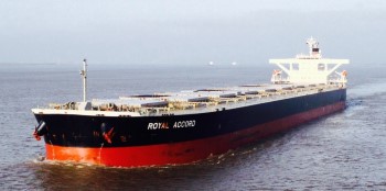 |
photo credits to www.fleetmon.com This is a good perspective of the ship. One of the things I really like about this ship are the interesting flying buttresses. | ||
 |
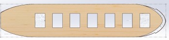
Original outline of Royal Accord. Notice there are nine hatches. | ||
 |
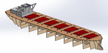
The model has been redesigned, keeping the bow and stern sections and the beam, and creating seven hatches, instead of nine. So the real boat would be something like 224 meters instead of 289. | ||
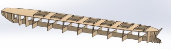 |
The keel is laid here. The bow will need to be fixed up a few times as the model is designed. | ||
 |
Here is a preliminary view of the bow. This just didn’t look right. | ||
 |
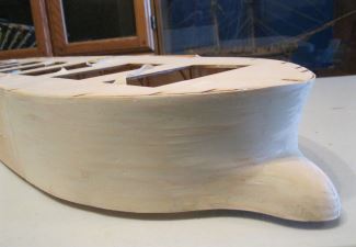
Finally, the bow seems to have taken a nice shape. | ||
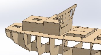 |
The flat surfaces of the superstructure are simple enough to design. Also, since the builder will add lights, there are passages in all the surfaces. |
From 3D to 2D and Laser-cutting
Finally, the 3D design is completed. A quick rendering, from the basic Solidworks colours, is sent to the client for approval. It sure would be fun to design a large version of a bulk carrier, for R/C operation, in 1/96 scale.
After approval, the 3D is converted to 2D for laser-cutting.
 |
With a bit of colour added. I really, really, need to learn to draw the 3D hull. | ||
 |
When working with multi-body parts, one needs to create a top-level property table. This table is propagated to the cut-list bodies where the bulkhead names, or any other property, can be added. These properties are then accessed at the drawing. | ||
 |
This picture shows the layout on the 12-inch by 24-inch plywood boards. |
The Drawing
I really enjoy making these 2D drawings and accompanying instruction drawings.

Assembly – Part 1
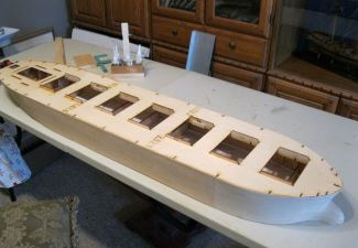
| The eventual client, the N-scale railway operator, felt that he did not have the skills to start the planking of the model. So, Part 1 of the assembly was done by a wonderful model ship builder in Cambridge, Ontario.
The planking is Spanish Sycamore, imported by Modeller’s Workshop for the many R/C modellers, who want long planks. |
|
 |
 a flat and straight build table. |
 |
 |
 |
 |