
May 14th, 2020
This nifty project is the design for the decks of a model of the Titanic in 1/144 scale, done using Solidworks 2020. The parts will be laser-cut from Baltic Birch plywood.
There is plenty of information on this ship so I am going to omit basic information and jump into the design process.
This set of parts is designed for a builder who wants to make a better model than that of the available kit of the same scale. The starting point is the excellent set of plans from Hahn.
Those plans can be obtained here: here.
So, let’s get to the design!
Phase I, the Original Scope of the Project
The original scope of the project was to create the following:
-Boat Deck
-Promenade Deck
-Bridge Deck with Poop and Focsle decks
-Shelter Deck
Pictures below will show the slow evolution from a simple project to something quite complex.
As I am a Solidworks user, I like to describe some of the issues I run into when using the software and the solutions that I found.
It turns out I am stubborn. Instead of taking a step back and asking myself how to do a job easily, I forged ahead with a poor solution to a simple problem. You see, there are cabin areas on each deck and I wanted to show those graphically in 3D as well as show them clearly in the 2D for laser-cutting, differentiating the lines that need cutting from the lines that need to be engraved.
Since I didn’t give myself enough time to find a solution, I used a method that was just very cumbersome; I created digital cutouts and added separate bodies to create the illusion of areas inside and outside the cabins.
Eventually, I found a much better solution using the “Split Line” feature. This will be very useful in future projects. More on Split-Line later.
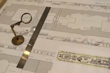 |
Here is a section of the
Taking careful measurements of the different parts of the drawings was time consuming but quite necessary.
|
||
 |
A section of drawing being inserted. The sections being inserted are at fairly high resolution, allowing for good precision when drawing. I try and keep within .03125″ of the original.
|
||
 |
My first solution to separating sections of a flat surface.
|
||
 |
Drawing overlaid over the part. | ||
 |
The same piece of the deck, showing the 2nd Class Entrance. | ||
 |
The original end result. This shows the four decks that were originally requested and the two well decks that are at the same surface as the Shelter Deck. |
Phase II, the New Scope
Once the four decks were completed, the builder asked me to make some connectors for him, spacers between the decks. Mind you, the builder has a set of parts for the bulkheads between the Boat Deck and the Promenade Deck and Between the Promenade Deck and the Bridge Deck but there are no parts to get the precise distance between the Shelter Deck and the Bridge Deck. So, the parts needed are the ones to set up a structure between the Bridge Deck, the two Well Decks, the Poop Deck and the Focsle Deck.
Uh, oh.
So, from where this was going to be a simple project, it took a huge turn into a deep hole.
Once again, I learned a lesson I’ve learned before, multiple times. I should have learned this lesson by now.
Jumping forward, I’ve added a picture of the Poop Deck parts. Note that there are no notches on the bottom edge of the face part. Also, notice that the slots in the Poop Deck are slightly longer than the tabs in the vertical pieces. This is so that the Poop Deck can be moved in relation to the Aft Well Deck.
Since I have not designed the hull itself, and there seems to be a small 1/8″ discrepancy between the plans from Hahn and what I think is the actual length of the Fiberglas hull, I’ve created the structure so it can be fit in place at the moment of assembly.
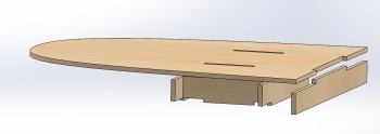 |
Notice carefully that there are no notches in the bottom of the face part. This allows the Poop deck to move slightly.
|
||
 |
Enlarged Aft Well Deck with slots prepared for the vertical connectors.
|
||
 |
Builders who would work with me can open my 3D files in a Solidworks eViewer. This is a free download and allows people I work with on new projects to visualize every stop of the design process.
|
||
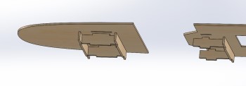 |
Here is a clear view showing how the slots in the deck are slightly smaller than the connector tabs. This will allow adjustment of the decks. | ||
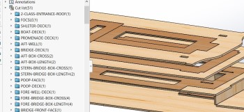 |
This nomenclature is fun while designing but makes it next to impossible to know what will be cut. | ||
 |
A lesson learned previously. Here is an older model with proper nomenclature. One has to wonder why we forget so easily.
|
||
 |
These numbers can now follow the production process through to the construction | ||
 |
At least with this, the builder should be able to put the right pieces in the proper place. Of course, the parts themselves are all engraved with the part numbers. | ||
 |
It is so much easier to use this feature to separate areas on a surface. It also looks much better in a quick rendering. |
Laser-cut parts
The parts have arrived and are on the way to the builder. I really like the way the large numbers turned out.
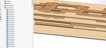
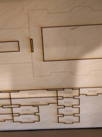 Fig.1 – A view including some of the connectors Fig.1 – A view including some of the connectors |
 Fig.2 – Nice clear numbers and bulkhead lines. Fig.2 – Nice clear numbers and bulkhead lines. |
Construction
Construction photos will be added as they are received from the builder.
← Back