Charles Mower Design #22

                                          Charles Mower design #22 – 1/8 scale – 42″ 

Thank you for your interest in this kit by Modeller’s Workshop, of Montreal, Canada. We hope you like it and hope you have as much fun constructing this boat as we had doing the research and the design. It has several interesting features that put this model in a new class of kit construction.

From Wikipedia, the free encyclopedia

“Charles Drown Mower (1875-1942) of New York was a noted yacht designer and author, and was at one time design editor of the Rudder magazine and a contributing author to Motor Boating magazine.

He started studying yacht design in 1895 with Arthur Binney and later Bowdoin B. Crowninshield, moving on to a partnership with Thomas D. Bowes in Philadelphia, Pennsylvania in 1911. During the first World War he served as a lieutenant commander in the Construction Corps, Naval Reserve.

After the war Mower worked either alone or in partnership as Mower and Humphreys Ltd. He was also a chief naval architect at Henry B. Nevins, Inc., at City Island, New York, and in 1937 was associated with the office of Nelson & Reid, Inc. He was also official measurer of the Manhasset Bay Yacht Club, the Cruising Club of America and the New York Yacht Club.

Most of his surviving designs are held in the Mystic Seaport Library, where a total of 433 sheets represent 107 designs.[1] A lot of his work was destroyed in the 1992 Noreaster and 1954 Hurricane Carol storms that attacked Connecticut. All of the surviving boat models once owned by Charles P. Mower (Mower’s son) are with Mildred Mower Pastula, granddaughter of Mower, and her sons; David, Stephen and James Osler. At times models have been loaned to Yacht clubs in Greenwich CT.”

The model is designed by Rick Shousha and is 1:8 scale and is 42 inches long. The kit includes the following features:

  • 27 bulkheads plus angled surfaces for the stern
  • Notches in all the bulkheads for internal stringers
  • A T-rail to ease construction of the model
  • A presentation cradle that is high enough to include the rudder and propeller
  • Front and rear benches
  • A subdeck with openings for the cockpit 

An optional parts package for the model includes the following 3D-printed parts:

  • 2 wicker chairs
  • 2 starboard chocks
  • 2 port side chocks
  • 6 small cleats
  • 2 large cleats
  • 1 dashboard
  • 1 steering wheel

The following parts are not included in the kit at this time: 

  • Running gear including propshaft assembly, prop, rudder, and propshaft strut
  • Motor and R/C gear
  • Prop shaft universal fitting

Designing the Model

The design started with a simple line drawing, and a few pictures. 

First, we create a 3D hull shape using software designed specifically for making organic shapes and then this 3D model is inserted into the manufacturing software, where we add internal parts as well as the designs for the parts that will be 3D-printed later on. 

Internal Stringer Design

The intention was to make a revolutionary kit design where the internal stringers look just like what they would on a real boat, and that is to have them follow the curvature of the hull. Most kits I have seen either have no internal stringers or they have a few straight ones. 

3D-printed Parts Design

The 3D-printed parts are available as a separate kit. Note, the cutwater is a fairly complex part. A modeller can use the part or can create their own chrome surface on the bow of the model. 

Setting up the T-rail and Installing the Stringers

A general list of tools you should have on hand: 

  • Building Board
  • Clamps clamps and more clamps
  • Dremel
  • 90 degree square
  • Bricks for weight – strangely and surprisingly useful
  • Metal straight edge
  • Glues of various kinds – I use titeBond II and 2 kinds of cyanoacrylate
  • Saran wrap – keeps stuff apart, if that’s what you want
  • X Acto knife and many spare blades
  • Long “aircraft” drill of proper size for propshaft (4mm?)
  • Japanese saws
  • Various very straight lengths of thin wood to use as battens to verify hull
    shape.

As with most models, one needs to be very careful with the beginning of the project as early problems tend to get magnified as an assembly progresses.

  • Remove all the pieces and verify that there are identifying numbers visible on each one.  Lay out all of the keel pieces, verify fit and orientation. Carefully verify that all frames and other basic parts are inventoried and available.
  • Where frames will show on the finished model, I typically rough sand each piece. Remember that the char from the laser cutting should be removed to allow glue to penetrate properly. Fine sanding to shape will be done at a later time. 
  • Assemble “T” rail and screw to building board. I use ½” self tapping screws and a straight edge to verify accuracy and structure.  Lay keel pieces out in proper order and glue together, this may take several steps. Use straight edge to verify. It is very important to make sure the structure is perfectly straight. Measure twice, three times, four times, before installing the T-rail. Weigh down on flat surface with clear plastic protection.  Sand after assembly.
  • Assemble frames and keel without glue to check fit eliminate any variations from fair curves (on the Mower there were none), clamp each frame to keel, while verifying that fair curves are not disturbed. I found that using the stringer locations and test fitting a few without gluing, is a
    great way to check alignments.
  • I cannot stress the importance of checking, checking and checking that,
    while fitting frames, all alignments are verified.
  • Glue with epoxy, wood glue, or cyano and leave overnight.

Once the alignment is completed and the keel is installed, it is time to install the stringers. Please note that the stringers are designed as decorative elements of the model. They will look really cool when the model is flipped over. This means it is important to make them look good where they will be visible but the ends themselves are not that important as they will not be seen. 

Stringer installation
  • Lightly sand stringers, as some will show, and it’s good practice anyway. I found the stringer installation to be totally straightforward, because of previous care with alignment, the stringers fit perfectly and this effort was completed in a day.
  • Again, I used cyano for this step. By this time, we are beginning to look like a boat, and it is time to think about any interior elements that should be installed while access is easy, and before planking.
Cutting the prop shaft opening

Although the location and slope of the propshaft is noted on the keel pieces, this is no longer easily determined. While the boat is still firmly on the building board, it’s a good time to drill for the prop shaft location. I have learned that the prop shaft should have no more than a 10% angle to the waterline (Needs to be verified)

Drilling rudder post location

Again, while the general rudder post location is easily determined, it is critical to verify there will be room within the boat for the rudder arm as well as the rudder servo before drilling the location. Future access to the rudder arm, as well as the servo, is also an important decision at this time.

Strake location – installation during planking

You will notice that there are notches in the last several frames at the stern of the boat for installation of the strakes. These will eventually be parallel to and just at or slightly above the waterline. Usually these are a fragile element of any model, but the notches allow for substantial strength.

Planking the Hull

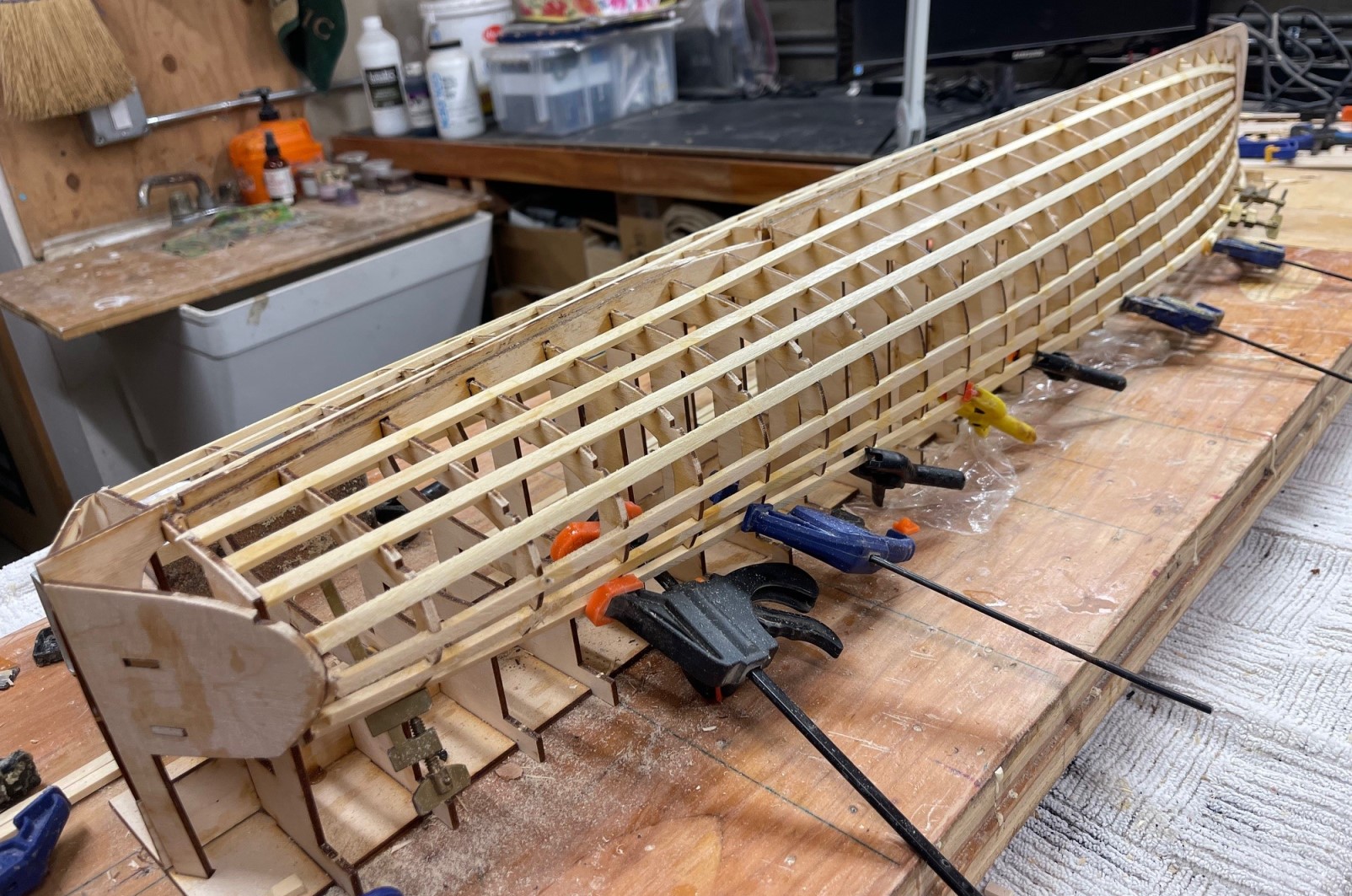
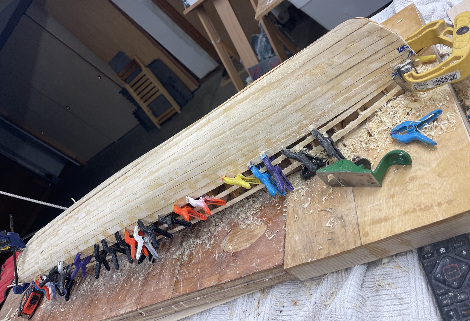
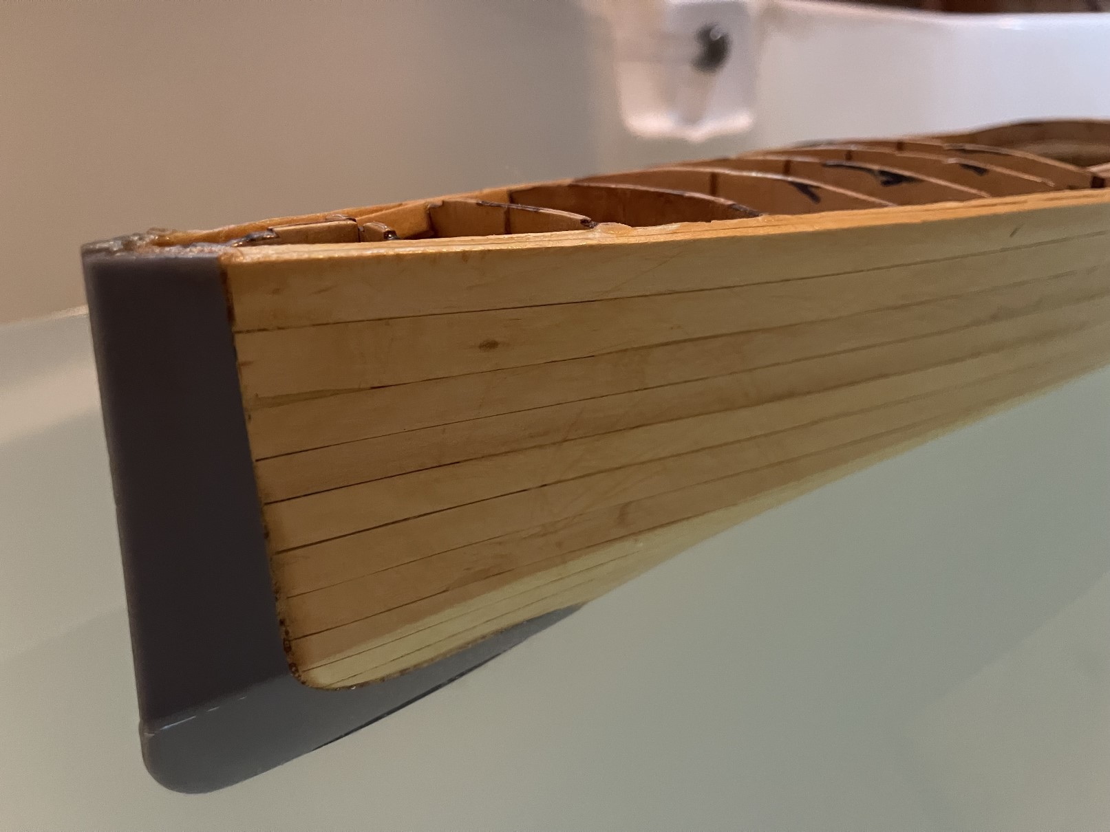
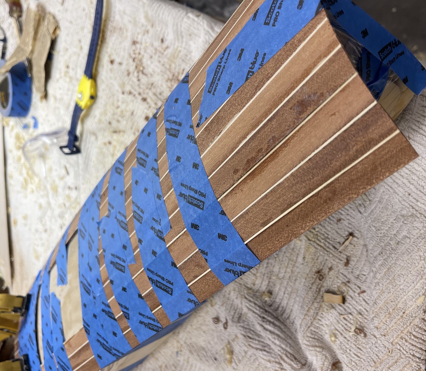
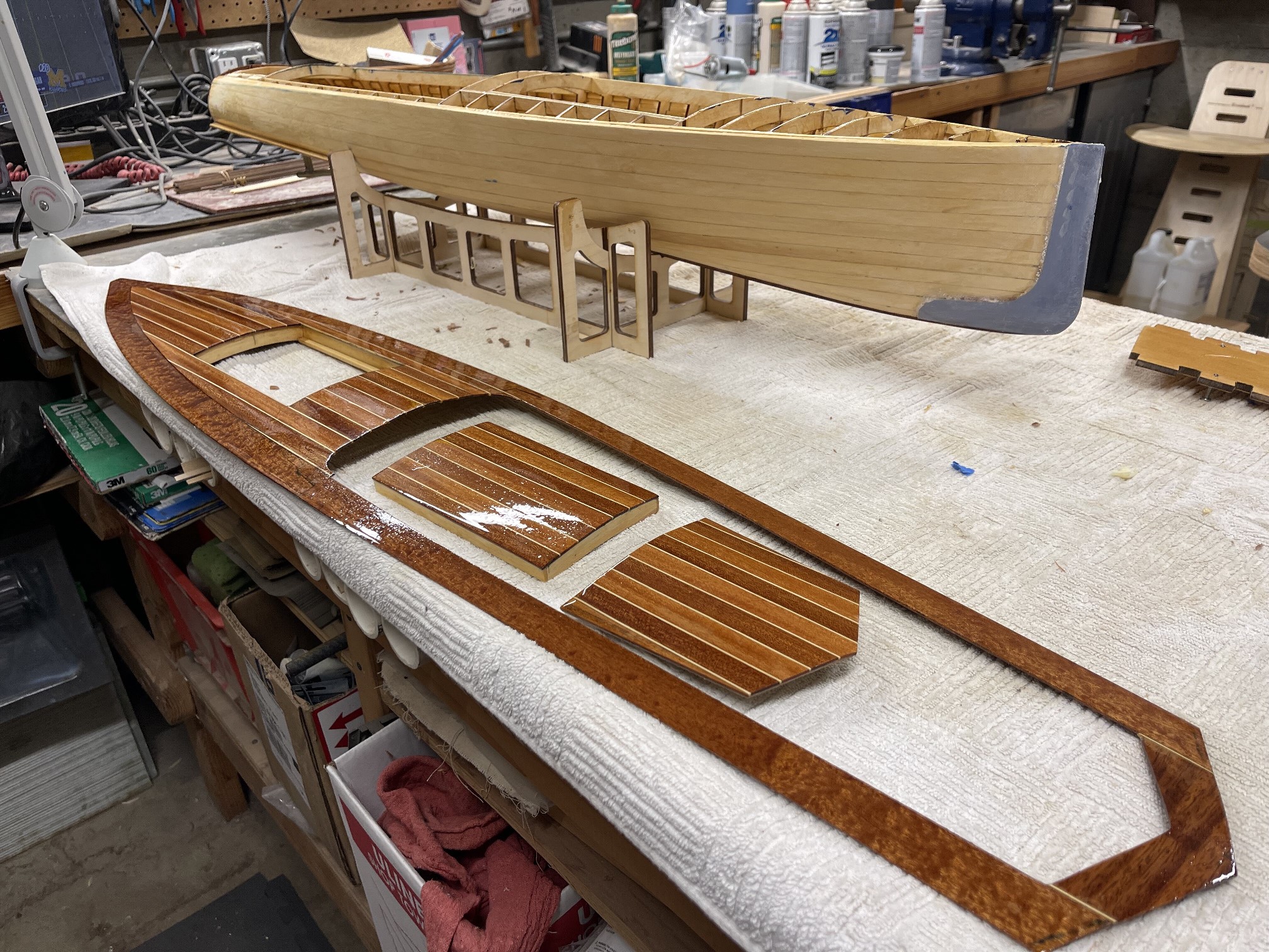
I use two layers of 3/32” x ½” yellow cedar for my boats.
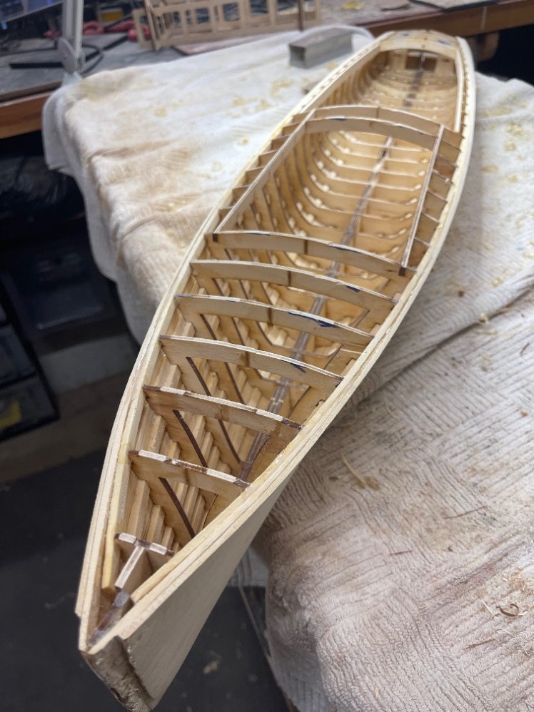
The frame dimensions have taken the thickness of the planking into account.
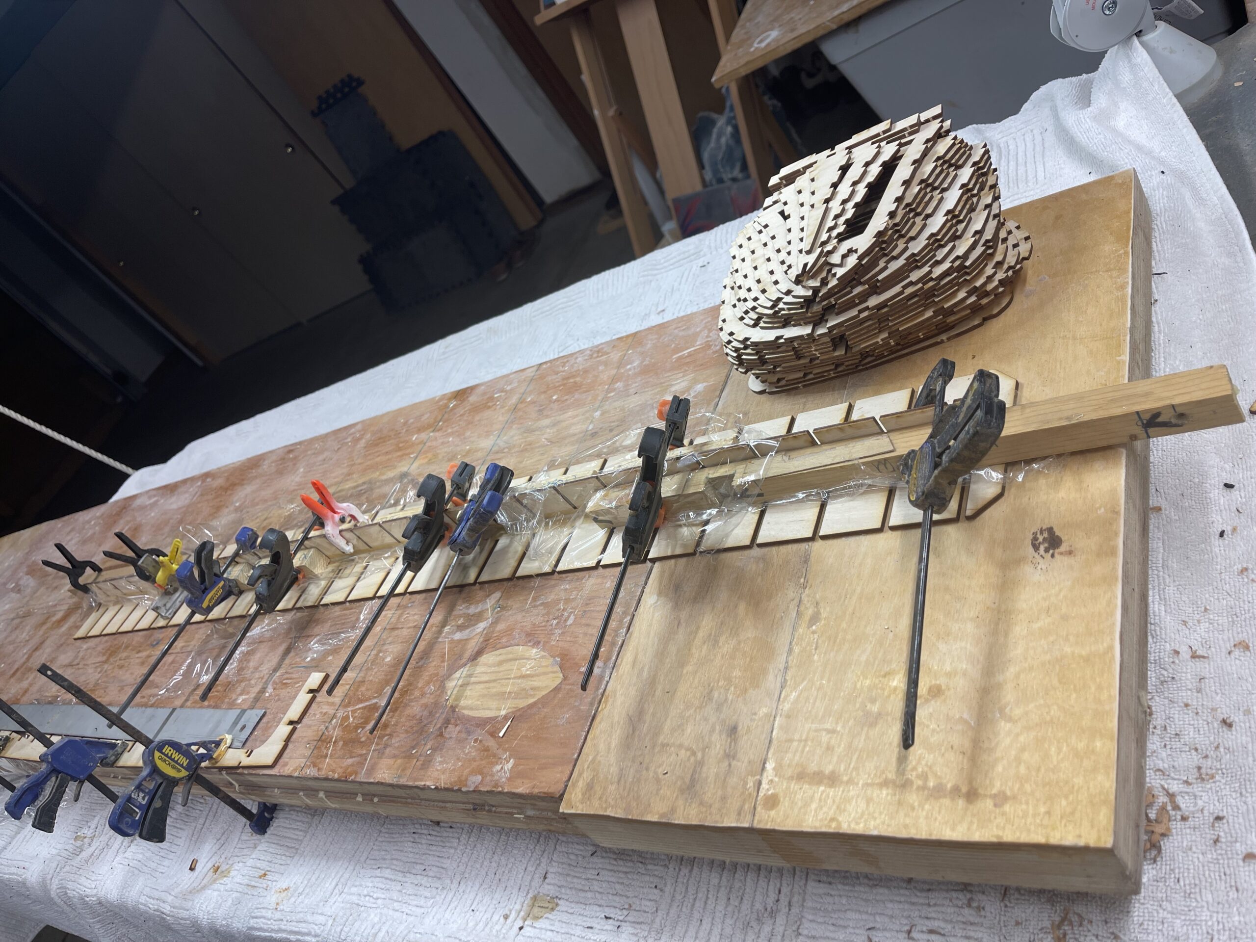
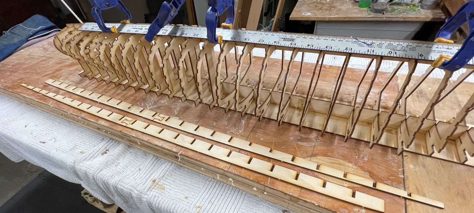
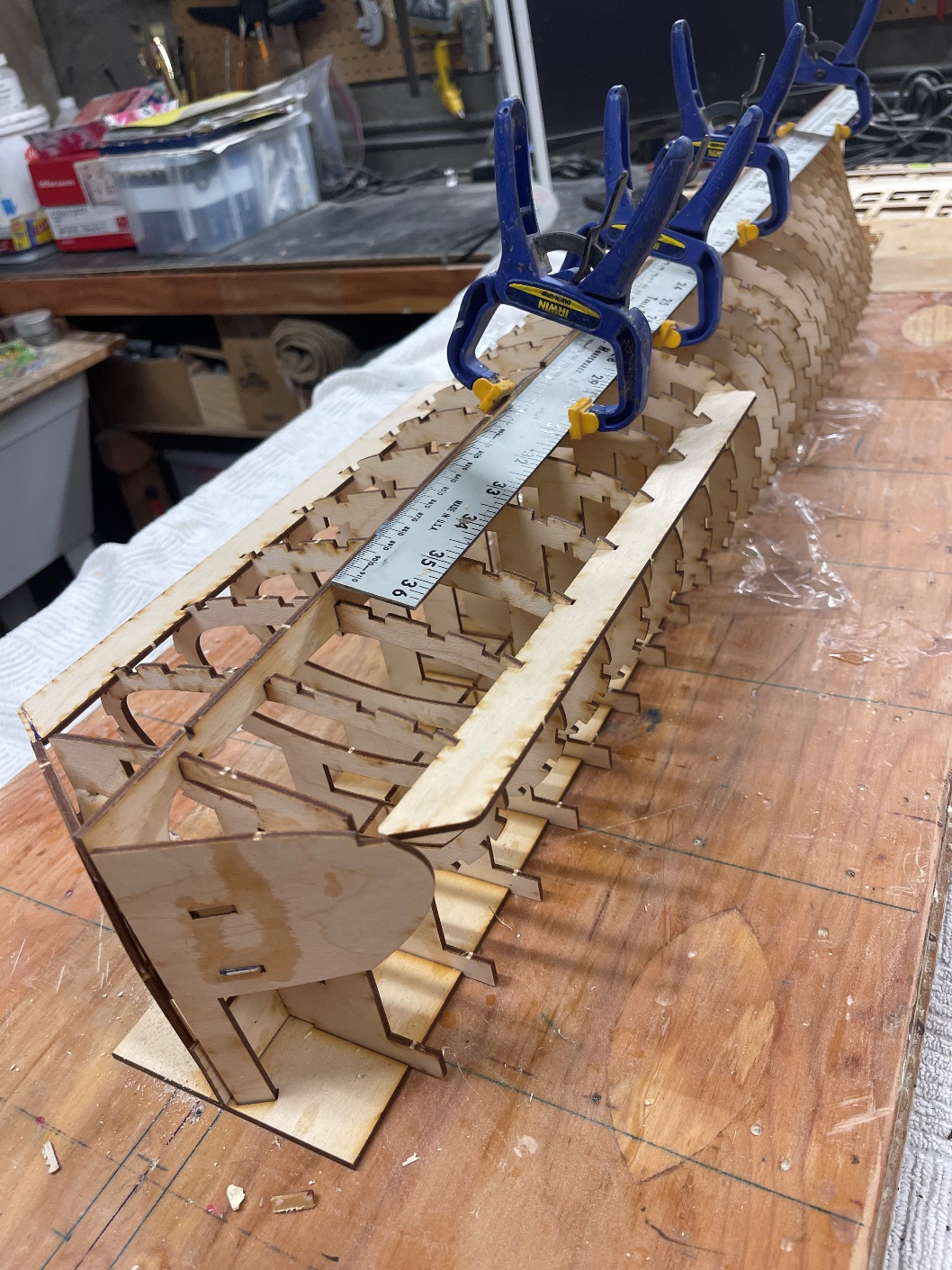
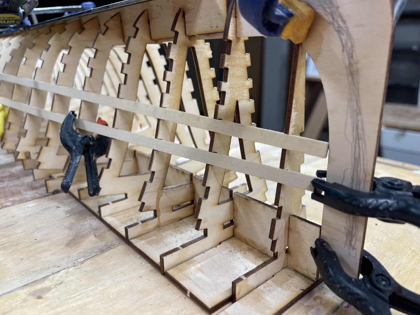
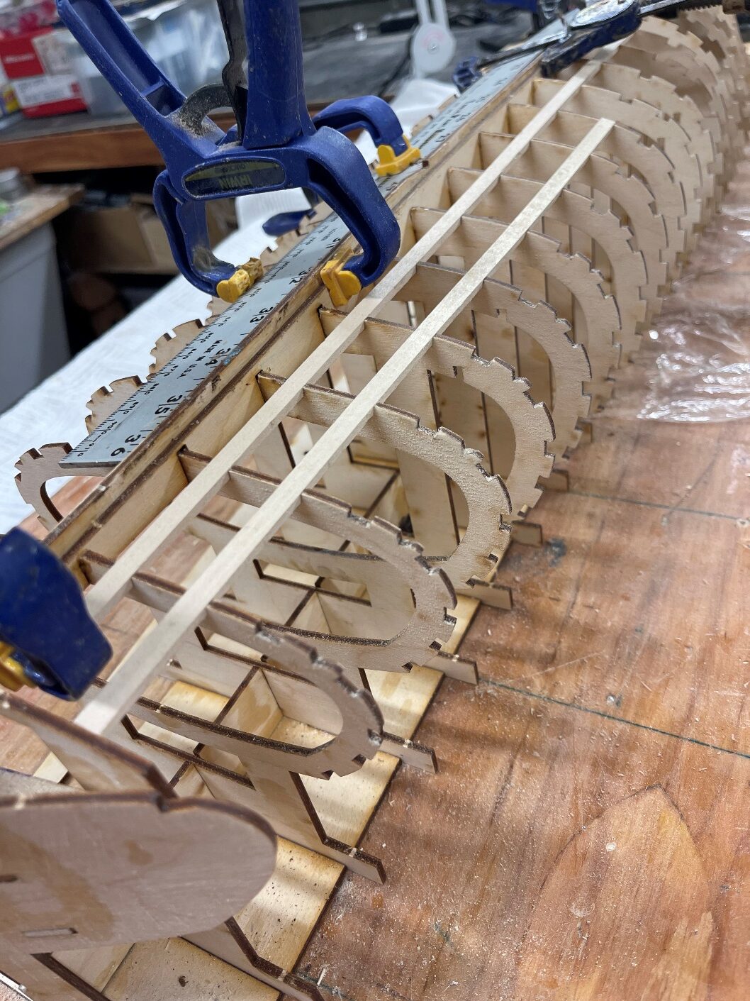
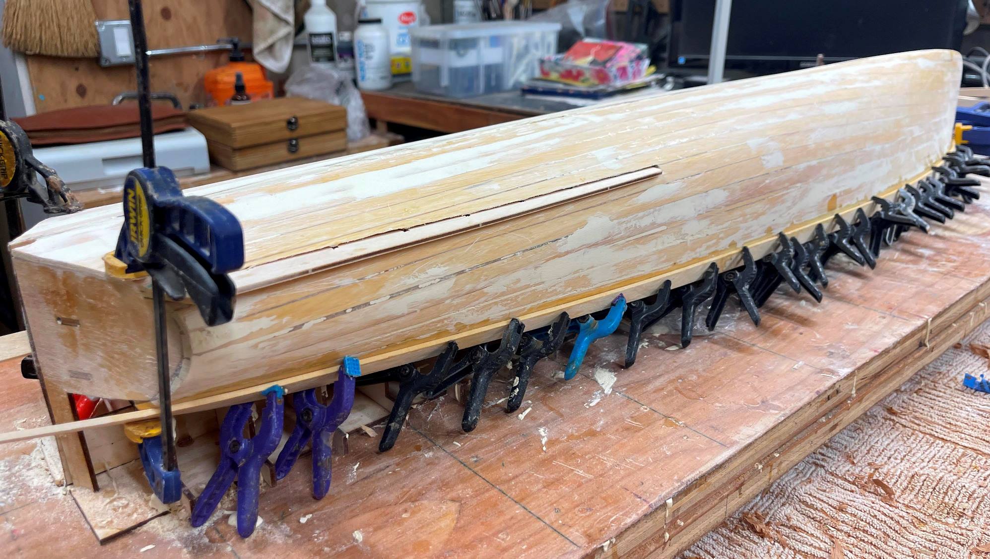
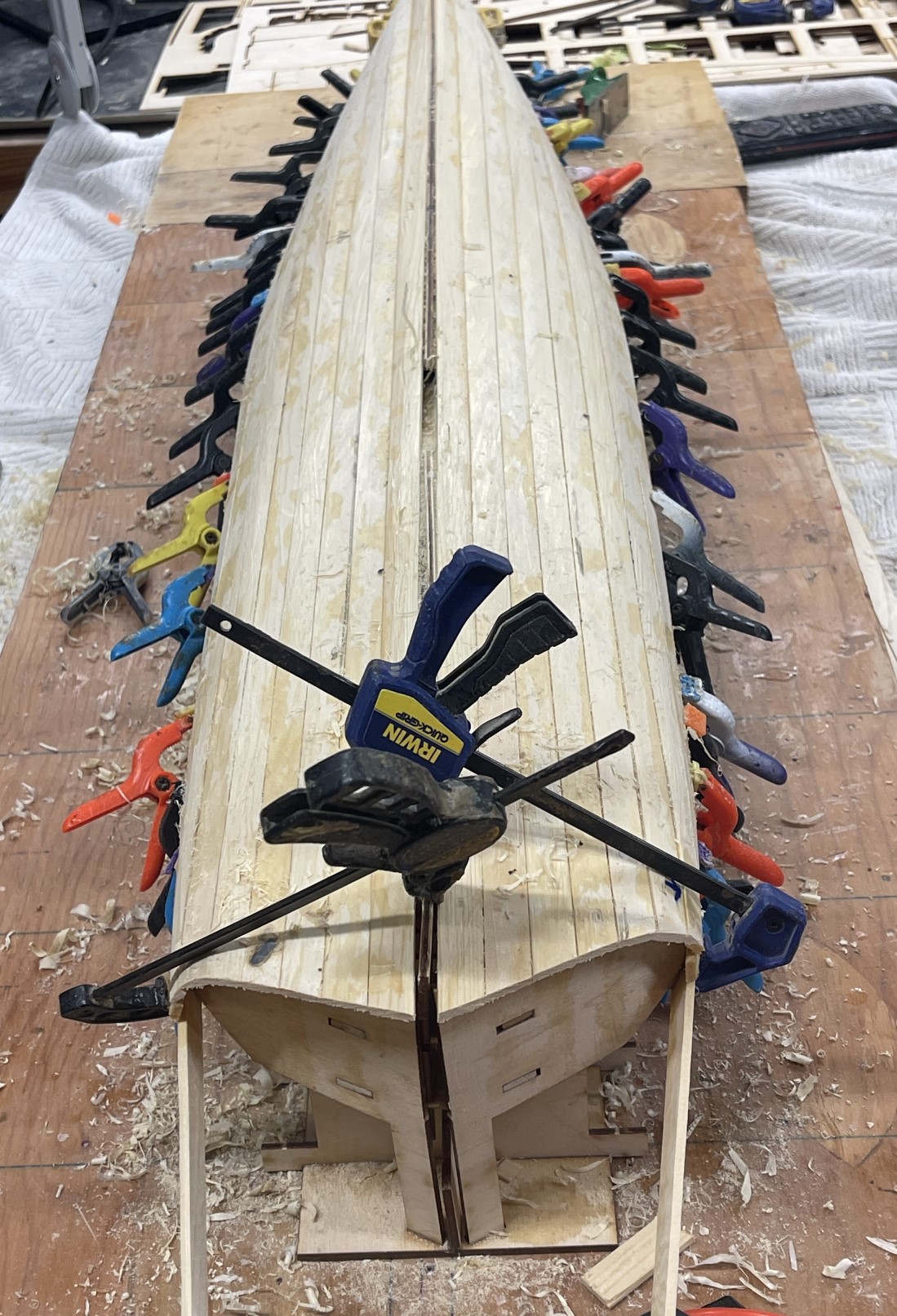
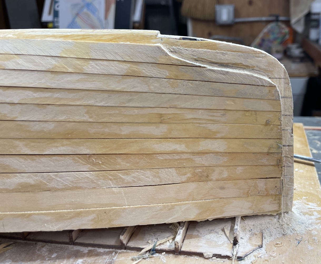
First step is to bevel all the frames so that stringers are just at the surface of each frame.  This is simply completed with a sanding block, 120 grit sand paper, some patience, and a light touch. I usually plank the first layer from the keel up to the sheer.

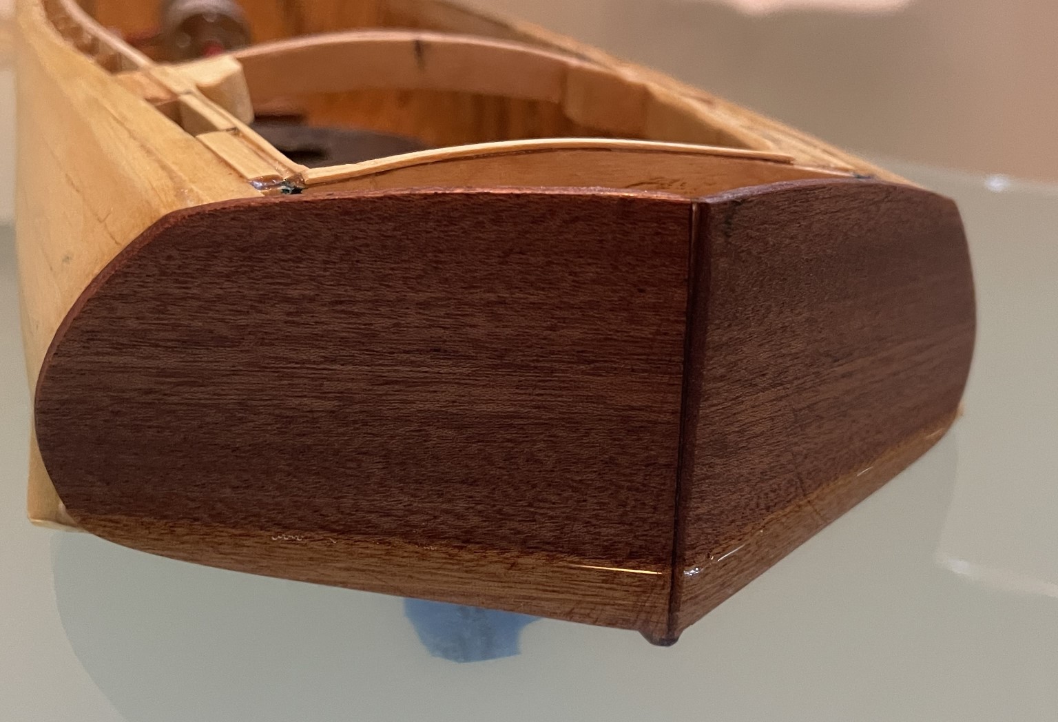
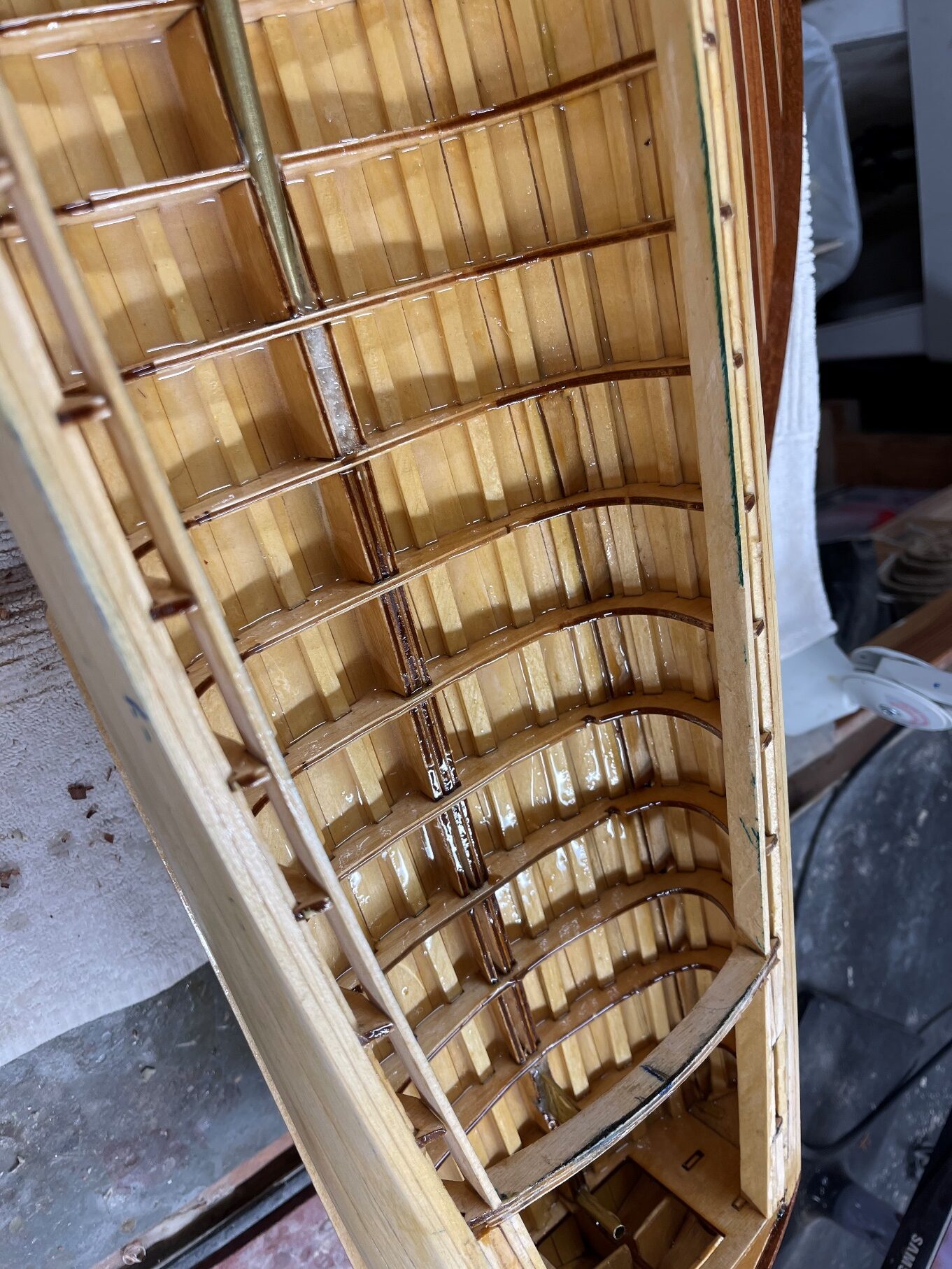
Following completion of this step, which, on the Mower, went remarkably quickly, with virtually no “spiling” of most of the planks, I fair the first layer, using easily sanded wood filler. This insures that the final layer of the hull is very fair with no bumps or depressions.  I then add the second layer, planking from the sheer down. I have found that using this sequence removes any chance that seams are aligned.

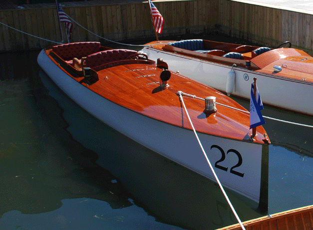
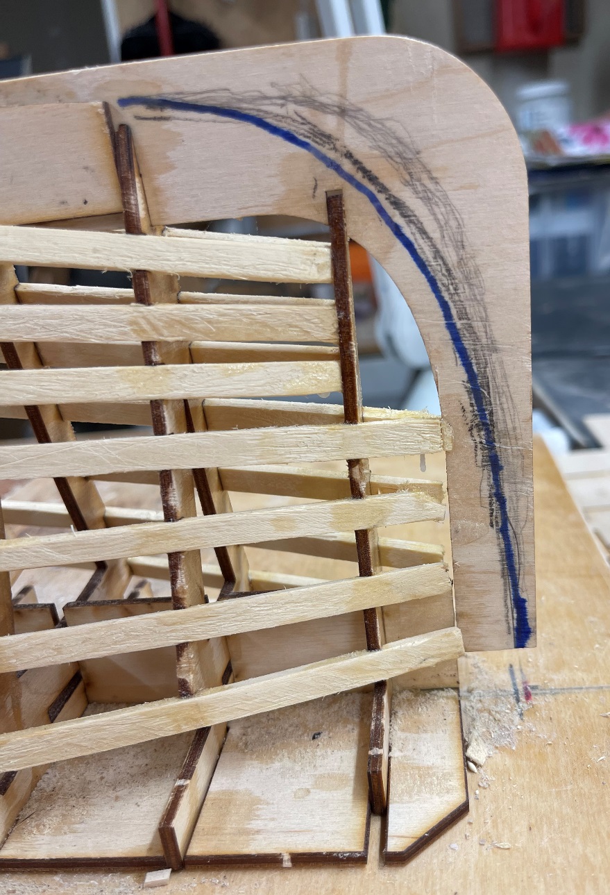
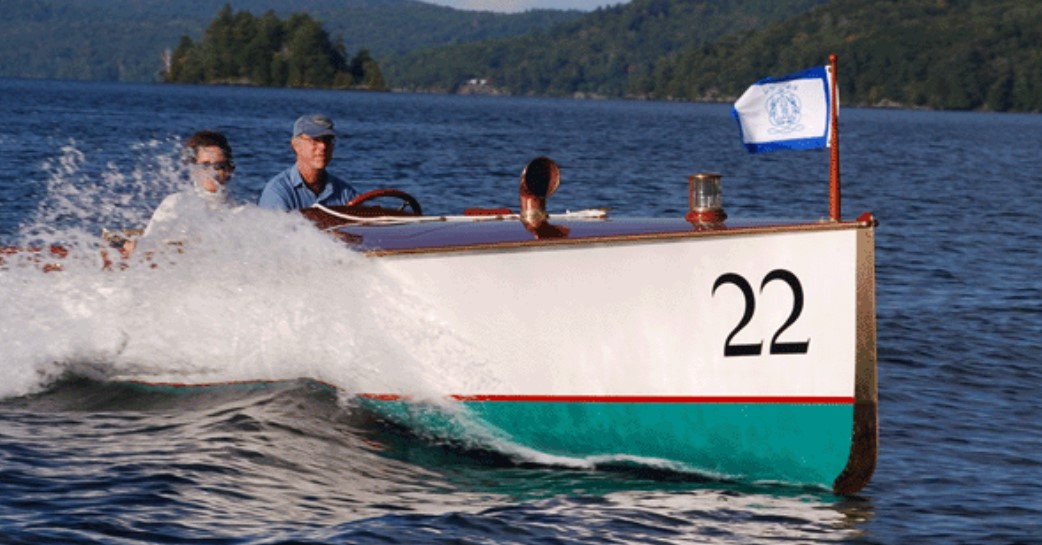
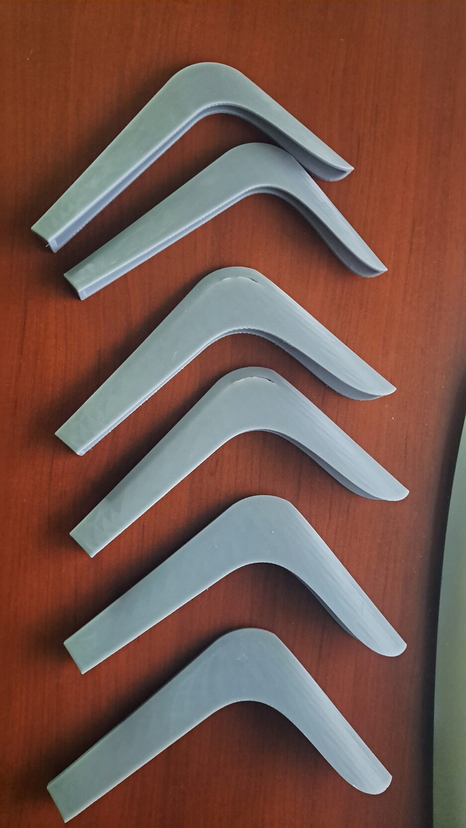
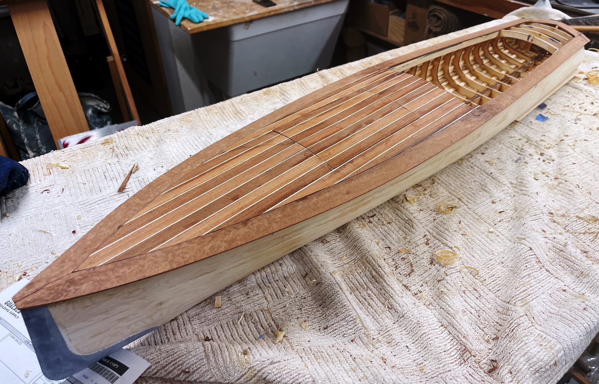
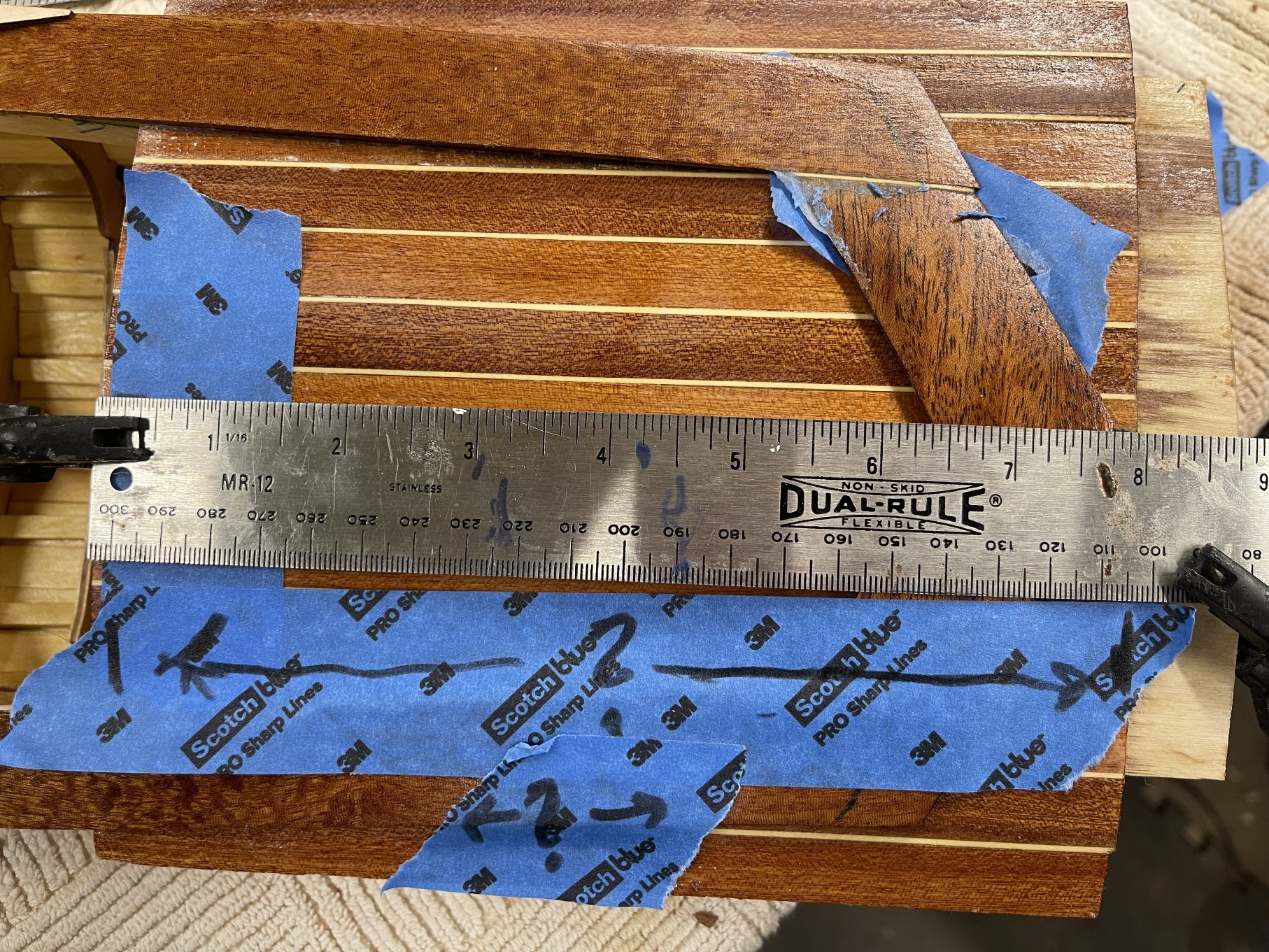
Don’t forget those cool strakes!

Locate and roughly clean up the strake locations as you are planking while you can still see them. Strakes will “slot” into these notches after some careful cleaning up and fitting. There are, at this point, two choices.
You may either:

  • 1 – Plank over the prepared notches and carefully reveal them after the
    planking or:
  • 2 – Test fit strakes and plank around them.

I chose option 1, which, while it took a long time, was a satisfying few hours of
fiddling. And they are strong!

Following completion of the planking, which, on the Mower, went remarkably quickly, with virtually no “spiling” of most of the planks, I fair the first layer, using easily sanded wood filler. This insures that the final layer of the hull is very fair with no bumps or depressions. I then add the second layer, planking from the approximate sheer down. I have found that using this sequence removes any chance that seams are aligned. Locate final strake location and fit strakes permanently.

Re drill prop shaft location.

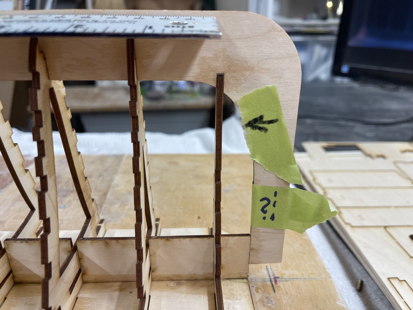
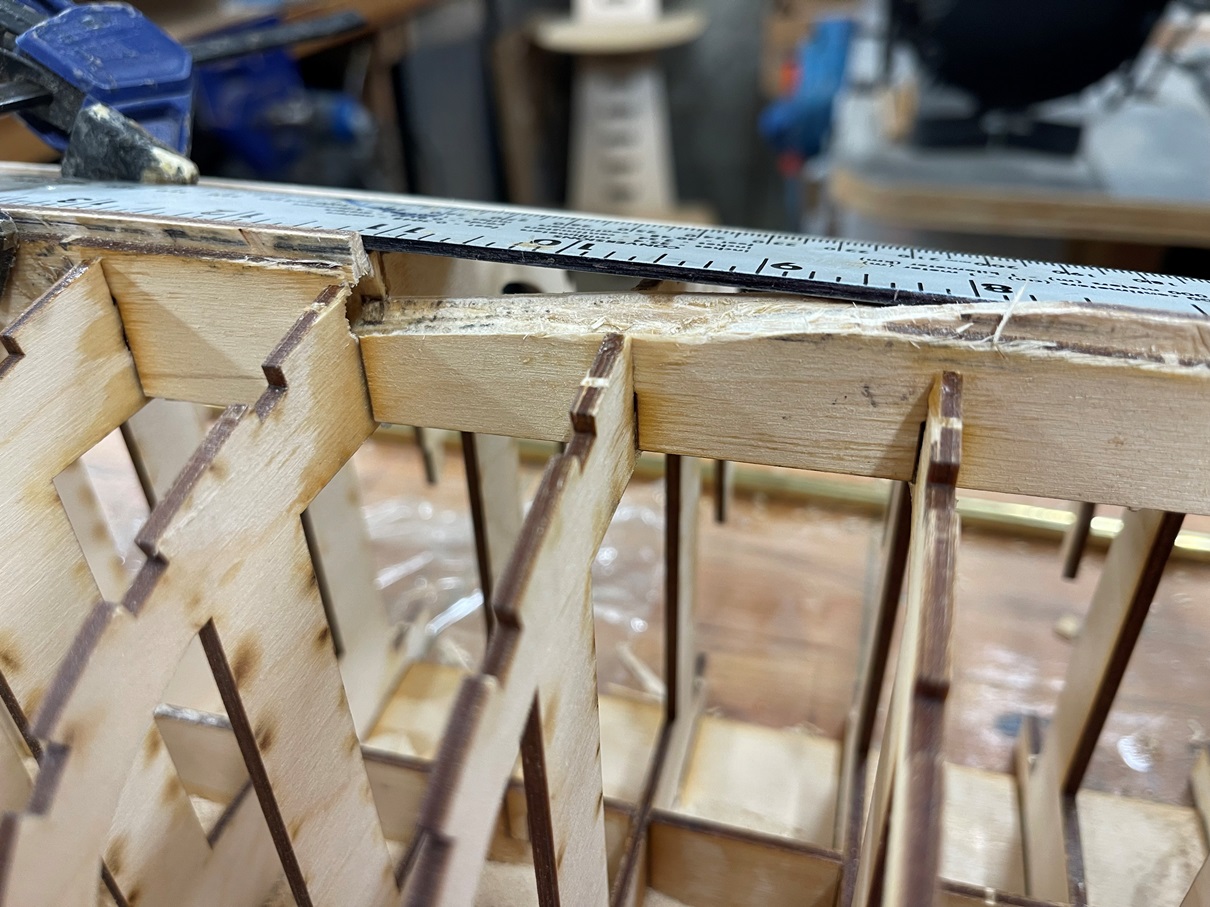
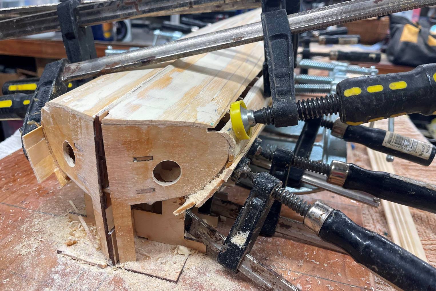
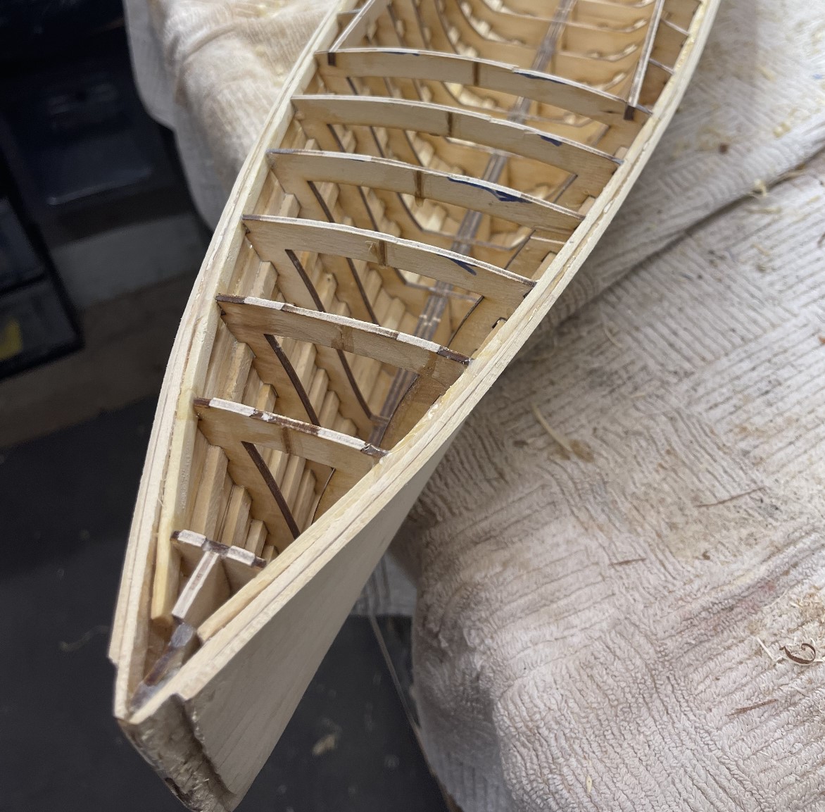
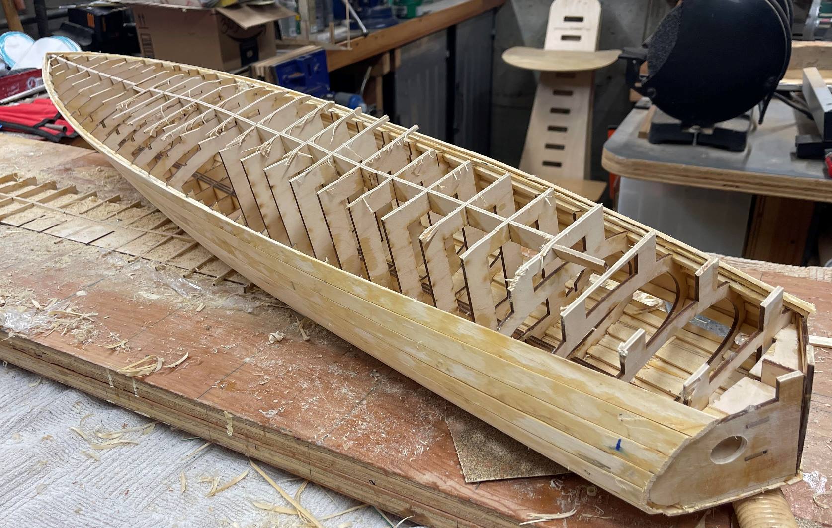
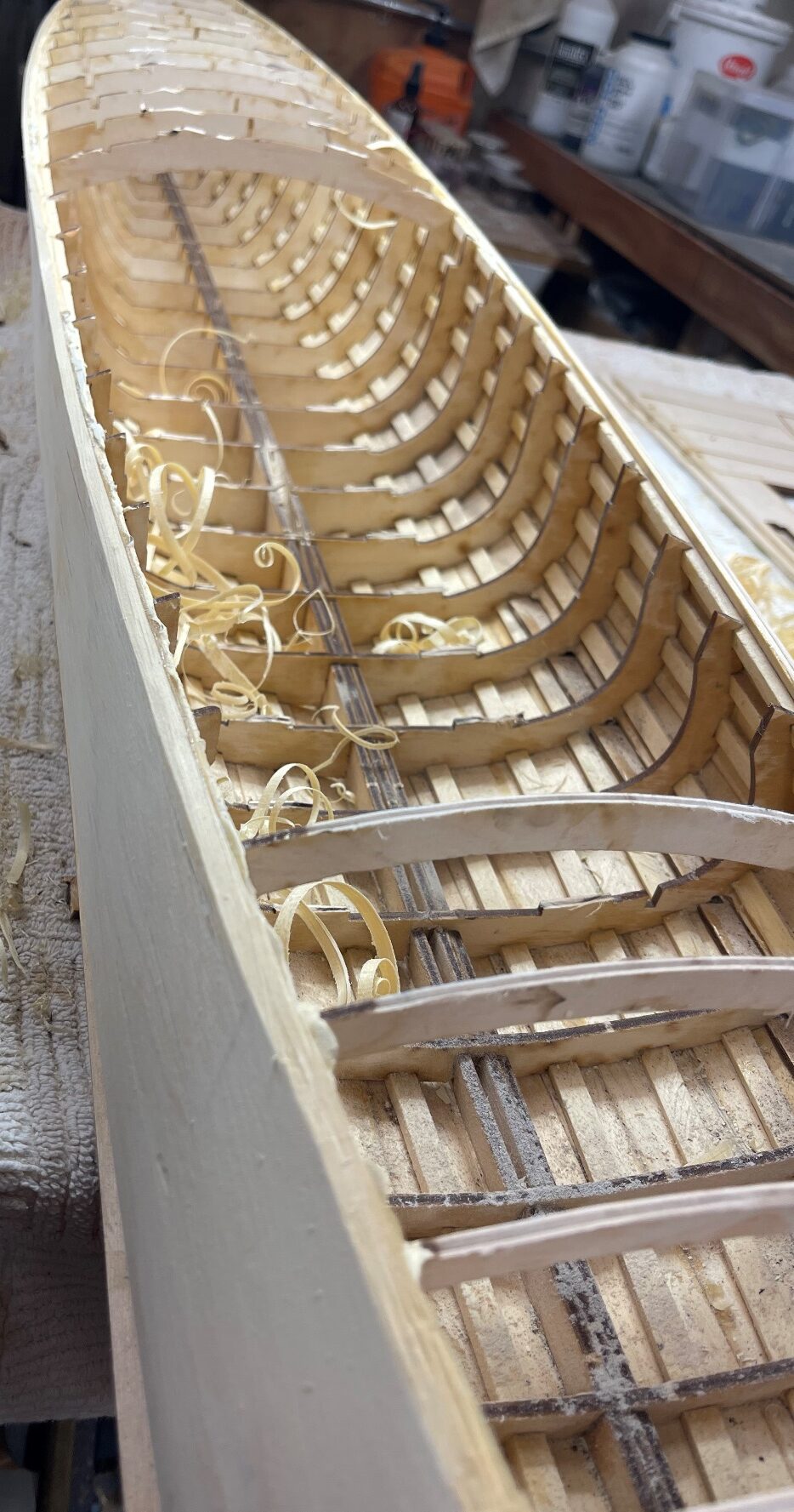
Removal of hull from building board

Its time to release th hull from it’s foundation. While, with care. This is easily accomplished (I use a Japanese saw) , it is also too easy to let the saw wander and start cutting into the carefully built hull. To this, I say, take your time, and verify each cut. There is a lot of excess wood, and it
can be confusing what to cut, and what is your precious hull. Remember, you will be cleaning up the frames and the interior after the boat is released from the building board, and access for final trimming will be much easier. Final trimming of the frames at the deck level will also establish the sheer line of
the boat, so constant use of a batten strip to carefully establish the sheer is
critical.

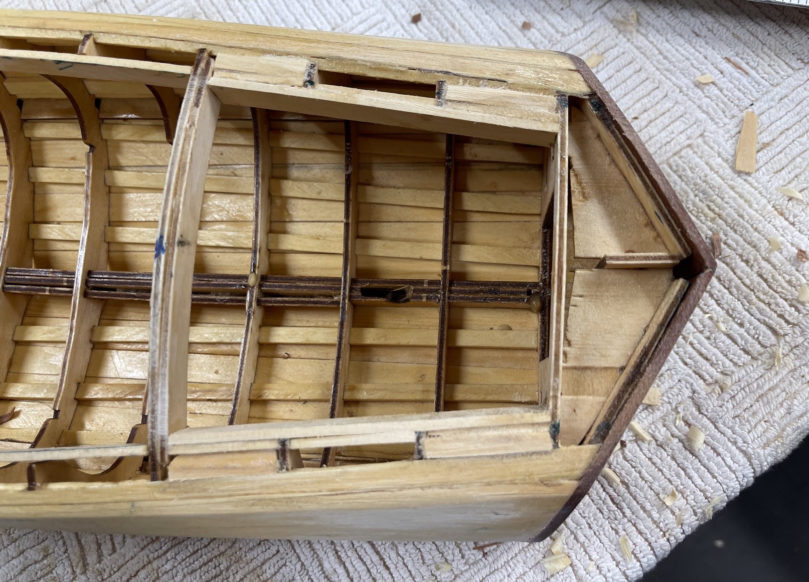
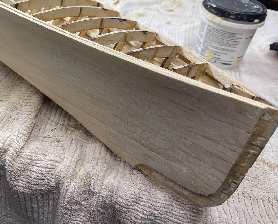
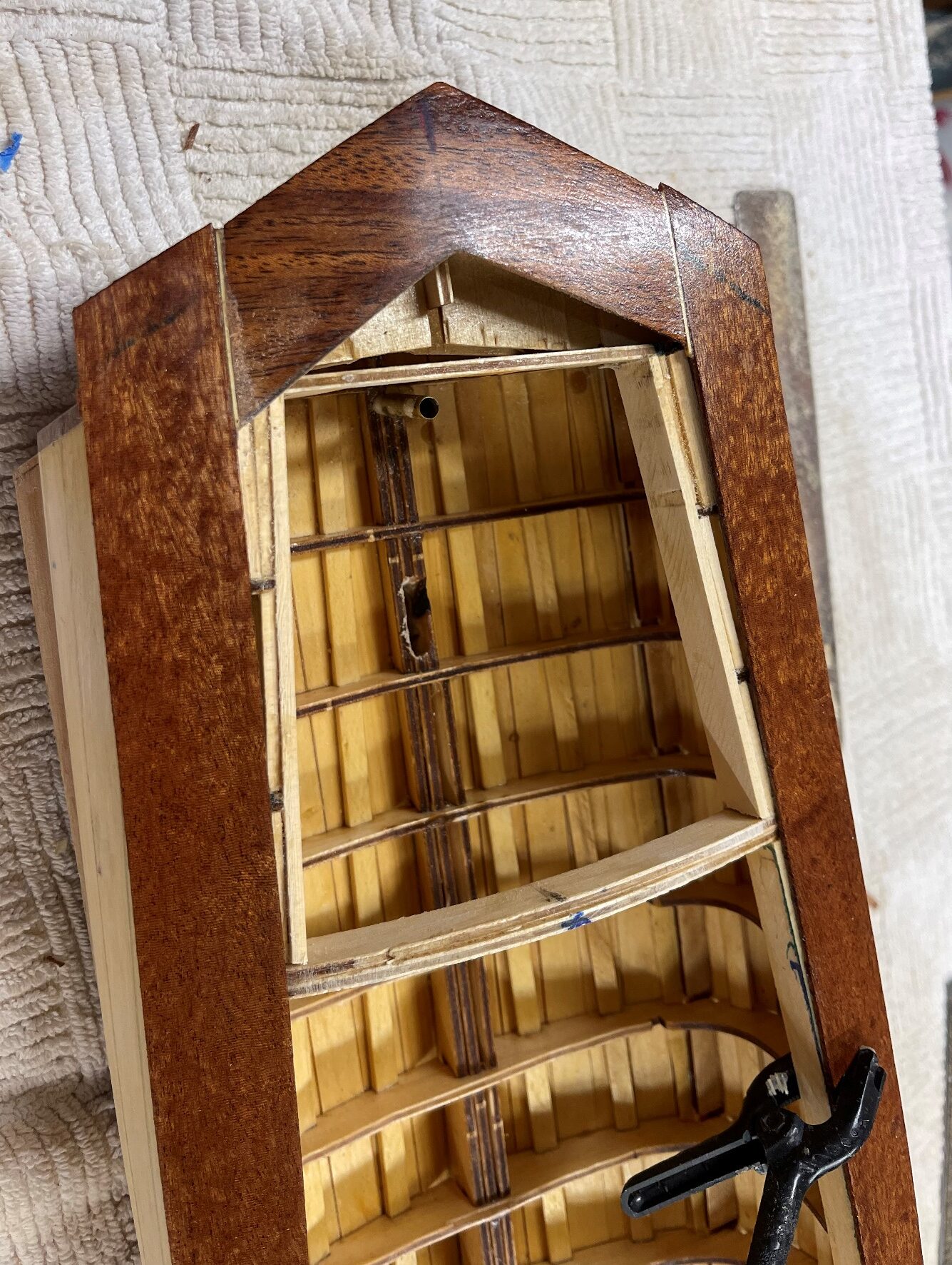
Epoxy boat interior and final hull fairing.
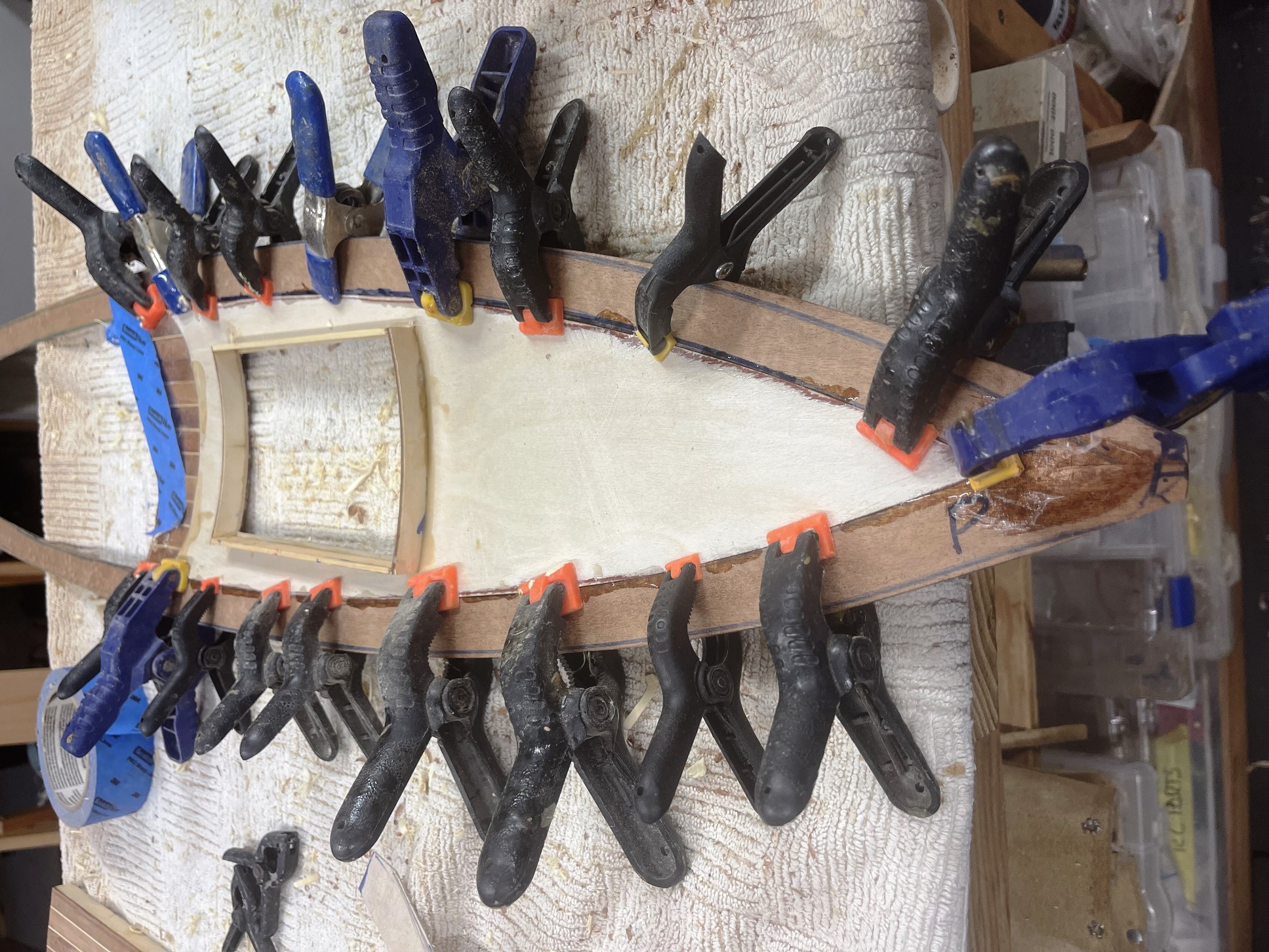
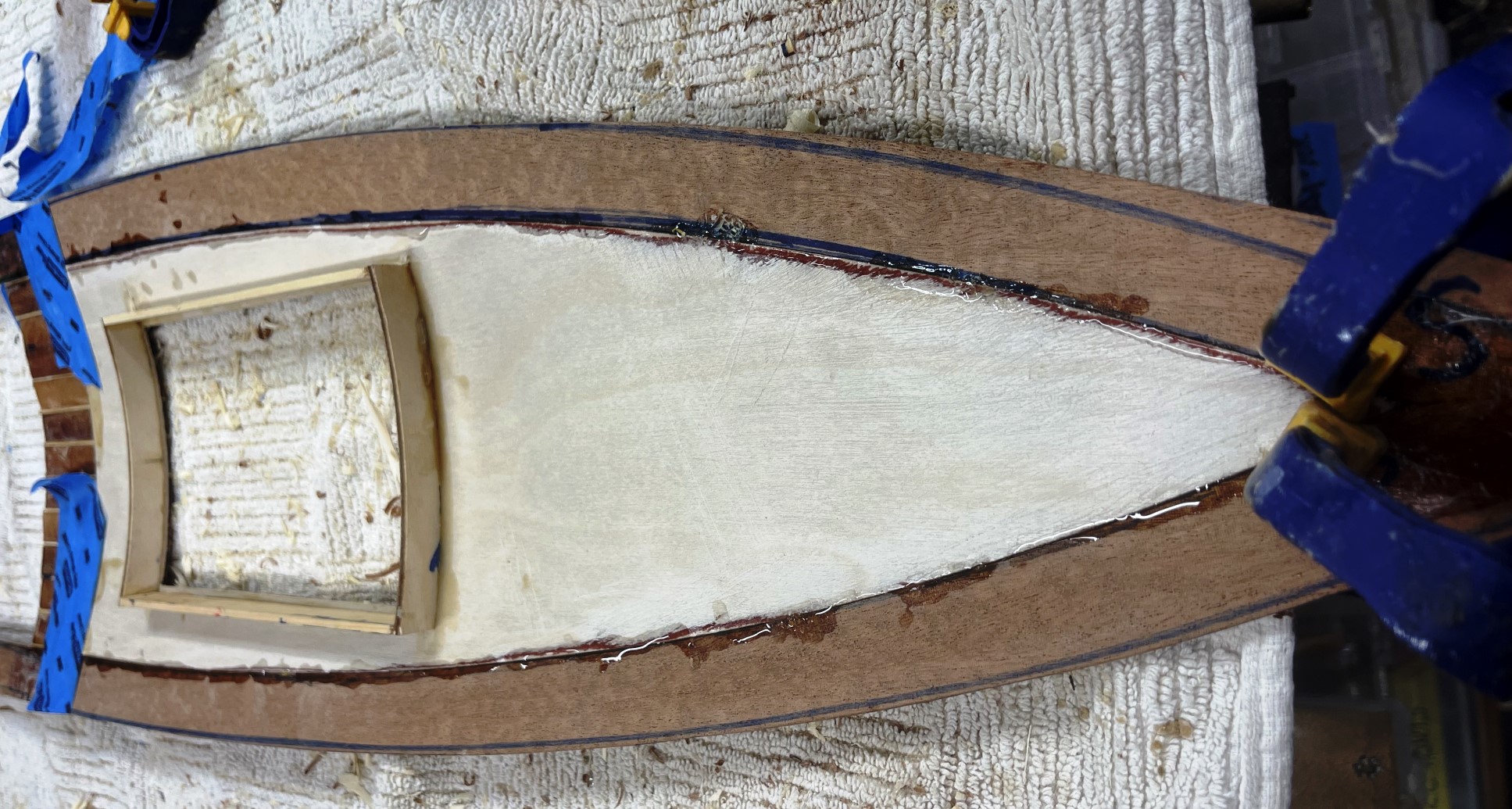
  • Now is the prefect time to seal the boat interior, while there is access to every spot. I use self leveling epoxy (table top) and make sure that is doesn’t flood the interior but certainly seals it. It dries to a wonderful flat surface. There may be some leakage to the boat’s exterior, but the is easily wiped off.
  • Once the interior is sealed, the exterior surface of the boat must be carefully shaped to create the final hull form, remove any high and low spot and locating the final sheer line. I use sandpaper, wrapped around wood blocks or sponges but care must be taken to remove the high spots, not accentuate the low spots. I usually go through several applications of very thin wood filler and many sheets of 120 grit sandpaper. I have also found disposable nail files very useful. (easy to find on
    Amazon). I go through 50 sanding down a hull.
  • I chose not to fiberglass the hull exterior, but used several layers of epoxy as the preliminary finish. This step creates a durable hull that avoids creating more dents and bruises while working on the hull. Seeing the final shape of the hull is very satisfying.
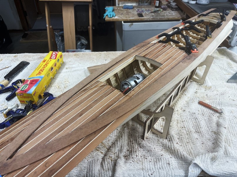
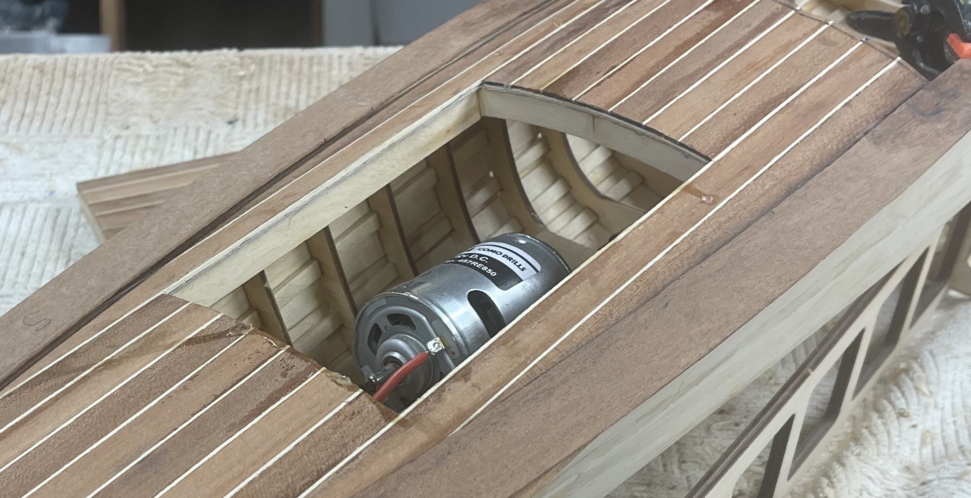
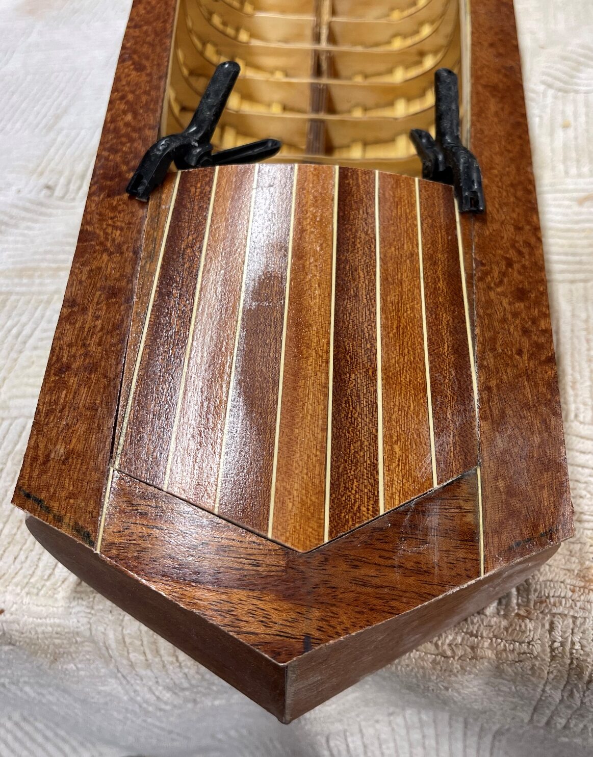
Fitting out the interior before installing the deck
  • Now is the time to attend to all of the various interior details that will not be easily accessible after the deck is installed. including installation of the prop shaft, the consequential motor mount location as it relates to the prop shaft, dashboard location, firewall installation, cockpit interior, rudder servo mount, concealed routes for various cord connections between future receiver, ESC motor control and batteries. Not only is finding accessible space for these critical for future enjoyment of the boat, but these elements affect the balance and performance of the boat.
  • Found that I would work on these issues while I was waiting for the deck pieces
    to dry.

Installing the Cutwater

I chose to fit the 3D printed cutwater after planking, although a case can be made
to fit it to the hiull before any planking or after the first layer of planks. Under any
circumstance, the cutwater fits flush with the hull..

Building and Installing the Deck

As with most models,

Tags:

Picture of Written by: Rick Shousha
Written by: Rick Shousha

Yup, that's me in front of the Gaspé, in Quebec

Latest Post

George Crouch’s Baby Bootlegger

George Crouch’s Baby Bootlegger From Wikipedia:  “Baby Bootlegger is an American wooden-built speedboat. It was designed by George Crouch for Caleb Bragg in early 1924, and

L.E.Fry’s 1909 Suwanee

L.E. Fry’s 1909 Suwanee The original boat is in the Antique Boat Museum, in Clayton, New York.  From the museum’s