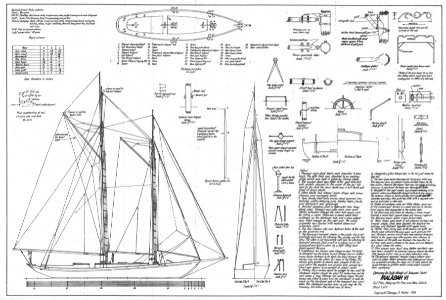
Malabar VI is one of the series of John Alden sloops, schooners and yawls which he
designed and used personally in the 1920’s, selling each after some time to build the
next.
Some of the earlier ones, including VI, were based on the well-known Glocester fishing
schooner form. In general, the boats evolved to become larger and more complex over
time.
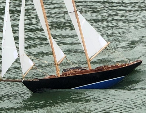
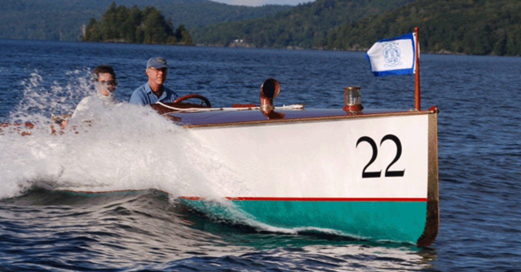
They were successful ocean racers and represent a classic look and character.
The specific selection of Malabar V! for this model was based on several criteria
The result of this selection is a stunning display, as well as sailing, RC model. Various
levels of detail and rig complexity can be incorporated in the build, ranging from simple
to highly detailed. For instance, the overlapping jib, requiring two winches, can be
substituted with one that is not overlapping, eliminating a whole level of engineering. In
addition, the detailed deck furniture can be eliminated for simplicity.
“John Gale Alden (1884–1962) was an American naval architect and the founder of Alden Designs.
Alden was born in Troy, New York, in 1884. At 18 years old, his father died, and Alden made the decision to train as a naval architect. He took courses at MIT and apprenticed with prominent naval architects Starling Burgess and Bowdoin B. Crowninshield,[2] starting in 1902.[3]
In 1900, his family moved to Dorchester, Massachusetts, where the Grand Banks fishing schooners were docked. These were said to have inspired his later designs.
In 1907, Alden undertook a voyage that would define his distinctive design trademark: The schooner Fame, owned by the Eastern Fishing company, had to be returned to Boston when her crew of 23 men had gone down with smallpox. Alden put together a crew of just four inexperienced young men and one old salt to undertake the journey. During the weeks that followed, they experienced extreme winter weather of up to 60 mile an hour winds that turned the salt spray to ice. The boat, and the crew, completed the journey and it is said that Alden learned how to design a boat that would be resilient in heavy seas and when a vessel was short-handed.
After the voyage, Alden returned to the Burgess offices but left in 1909 to found his own company, the Alden Design Office in 1909.
The approach Alden took was to discuss requirements with the clients, make the initial sketches and then hand over the work to the draftsmen to complete. Therefore, each boat designed by the firm had Alden’s individual style stamped on.
By 1932, the Alden Design Office was known around the world due to the success of the “Malabar” designs in the offshore racing scene. Over the next thirty years, Alden designed over 1,000 boats,[4] including the 63.5′ schooner When and If for General Patton,
Alden retired in 1955. The Alden Design office carried on until 2008, under the helm of Niels Christian Helleberg, naval architect.[1] Helleberg continued providing design and print services until closing his office in January 2014.[7][8]
Alden continued to race into his seventies, and enjoyed sailing one of his Sakonnet One designs until his death in Florida at the age of 78. His designs were donated by the company to MIT‘s Hart Nautical Collections.[3][9]
Alden was inducted into the National Sailing Hall of Fame in 2013.[10]
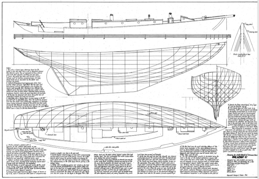
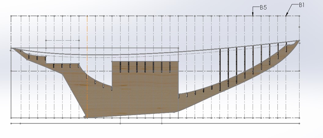
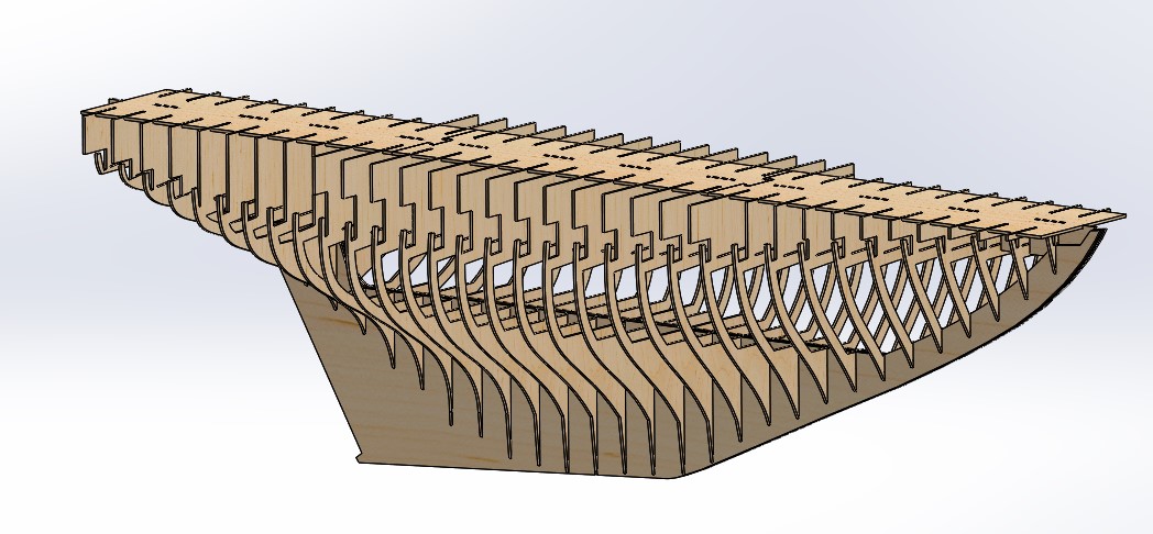
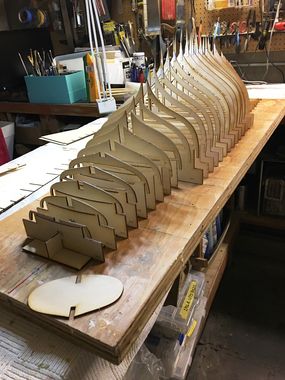
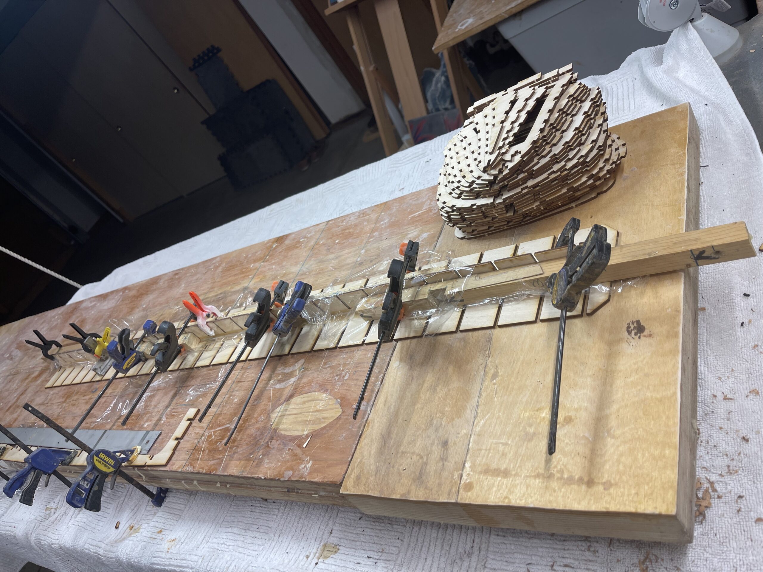
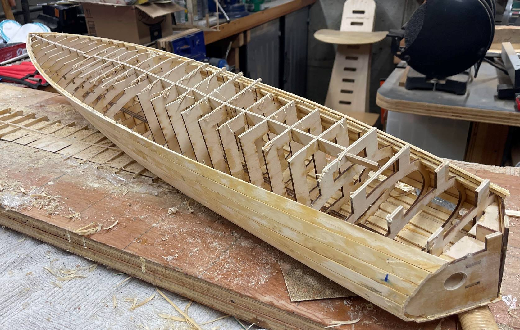
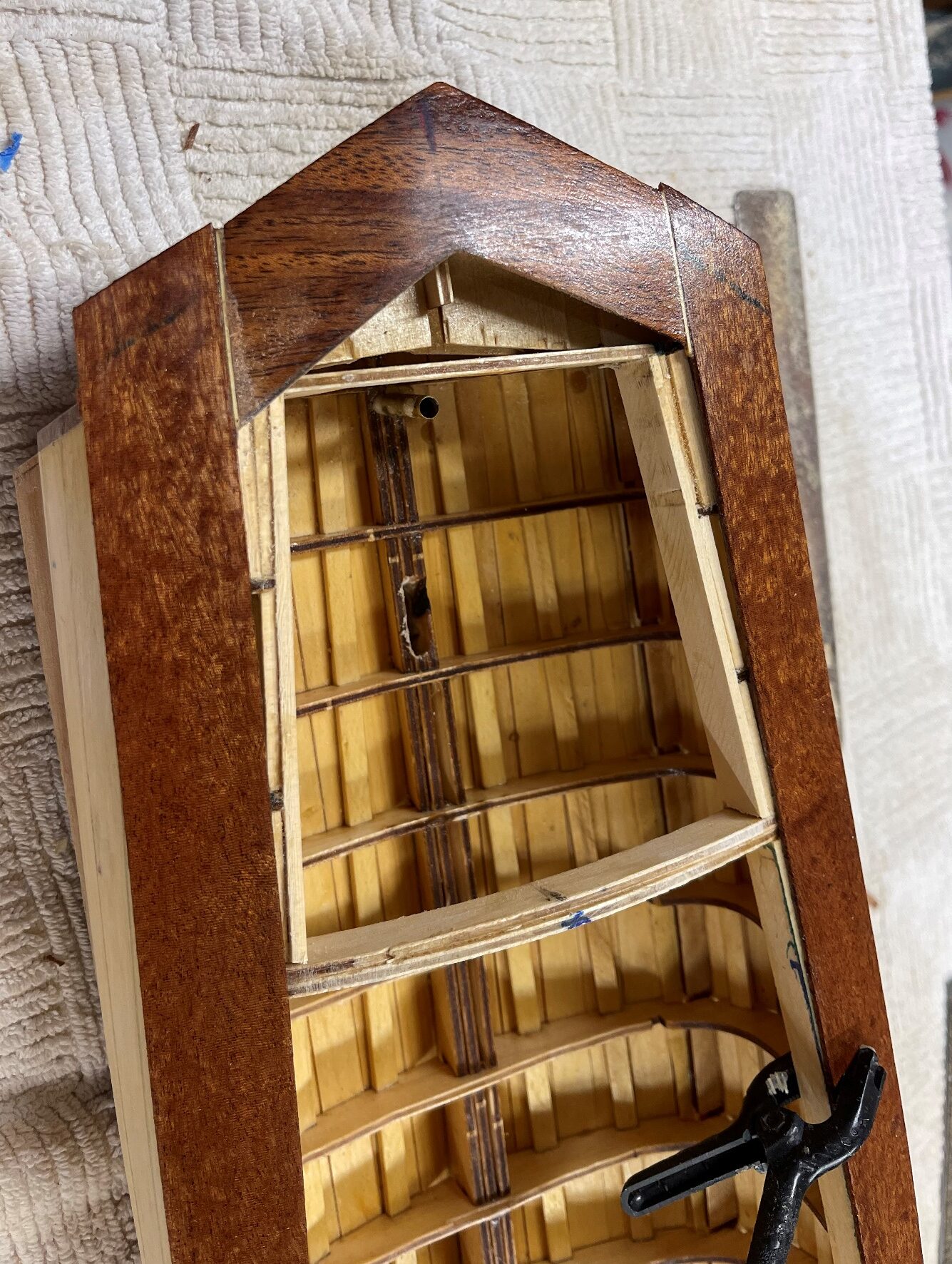
The design intent of this model was to create a hefty model that would look realistic as it sailed in a typical light breeze. This led us to increase the underwater volume slightly, and also to create a centerboard box in order to allow the insertion of external ballast. The keel is composed of four layers of 1/8″ plywood.
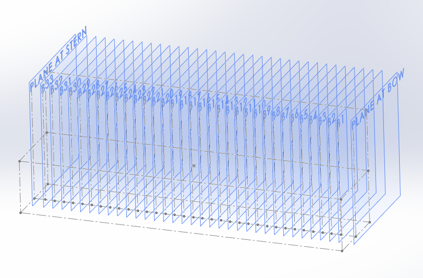
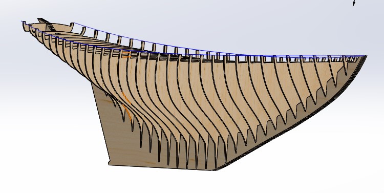
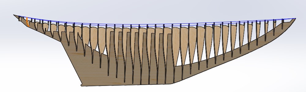
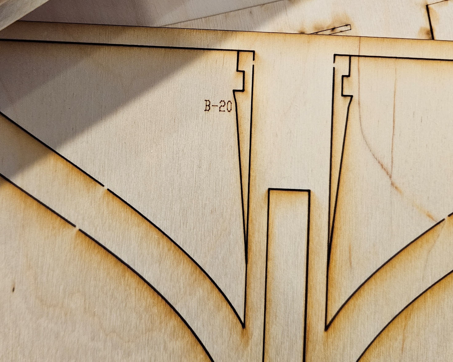
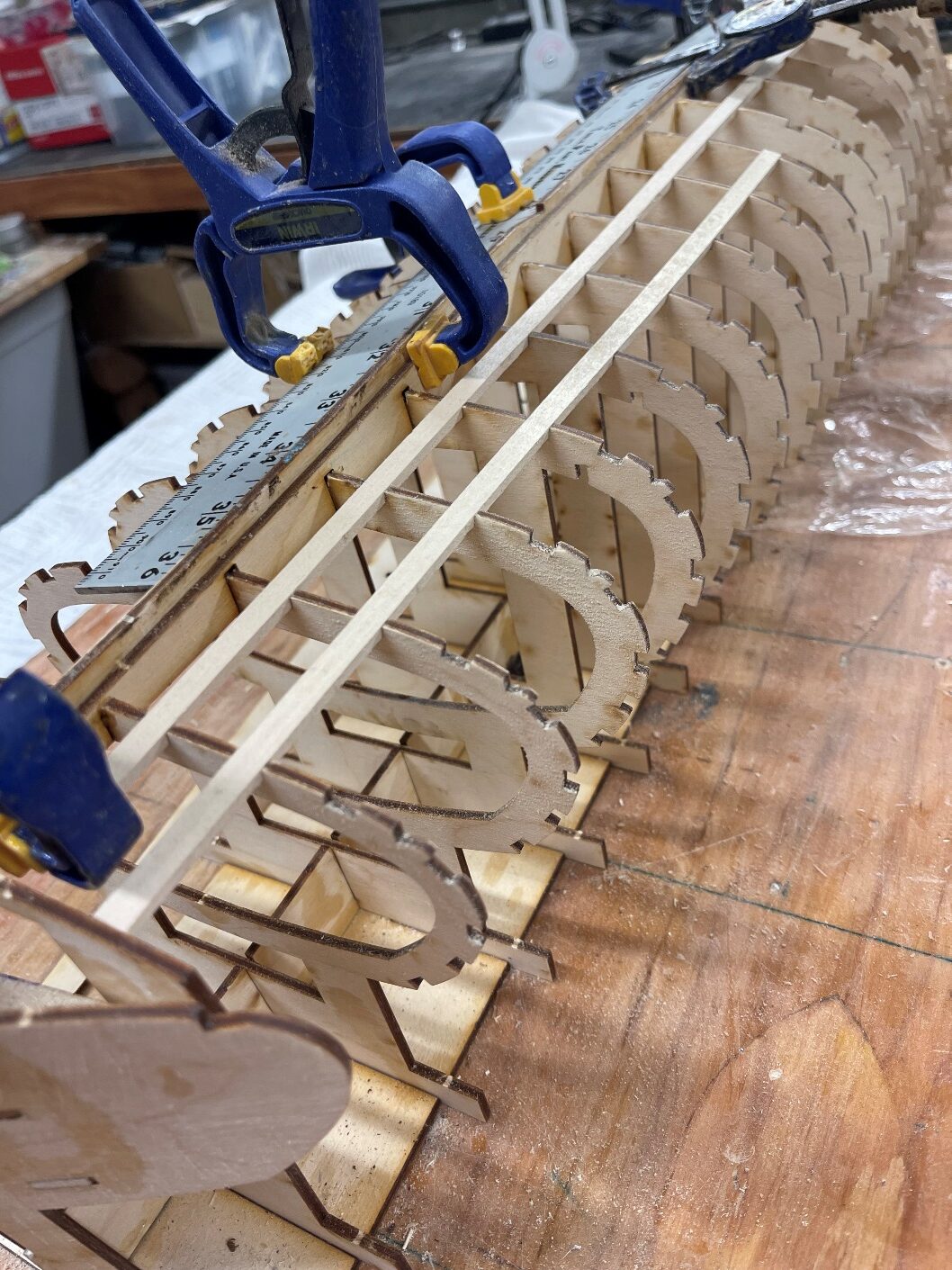
The frames themselves are all made of the same 1/8″ plywood.
Starting with a drawing that may have been intended for a smaller model, we doubled the number of frames in the original design.
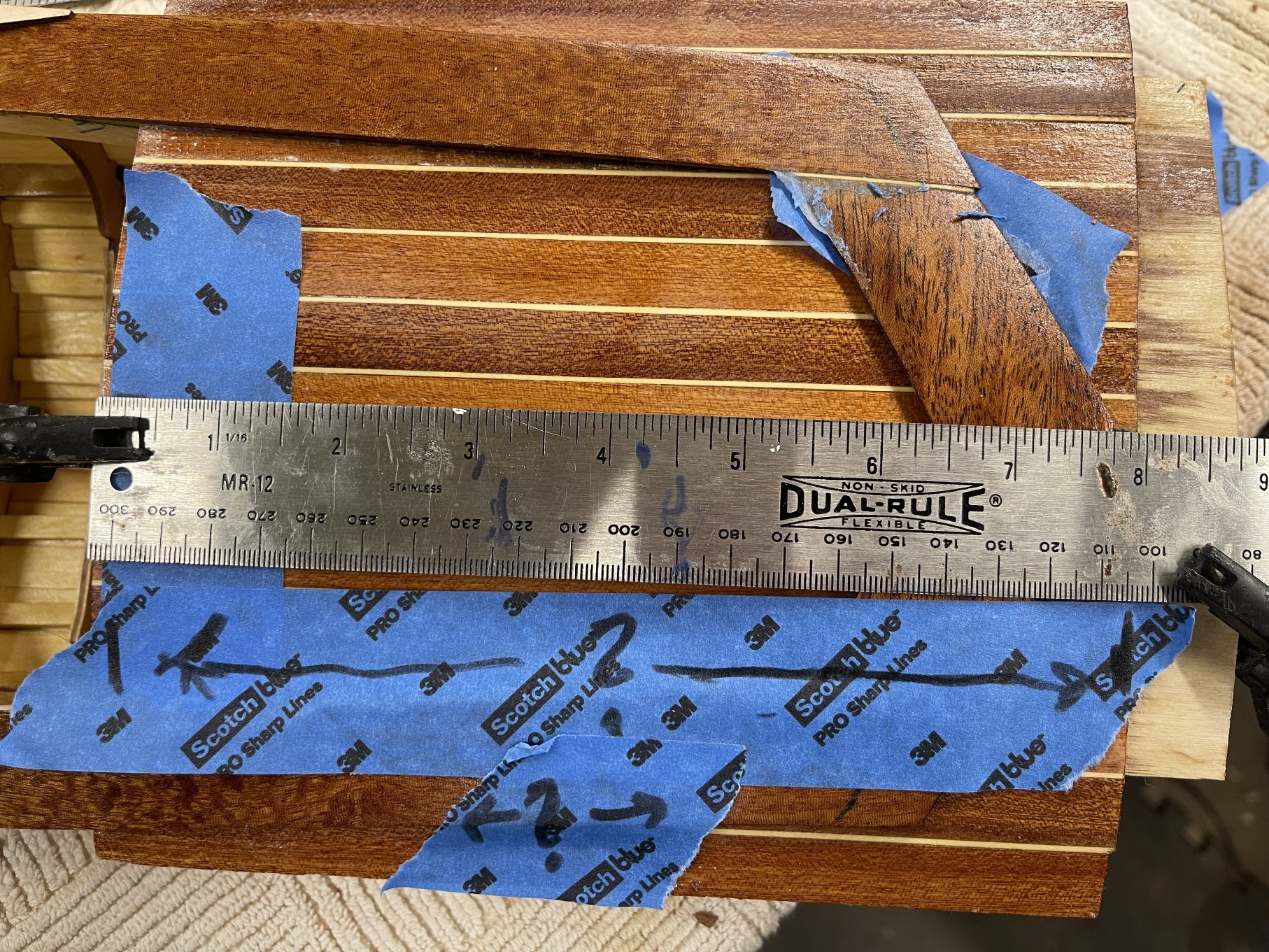
Discussion about the installation of the T-rail and planking goes here.

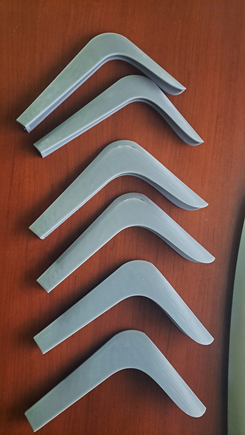
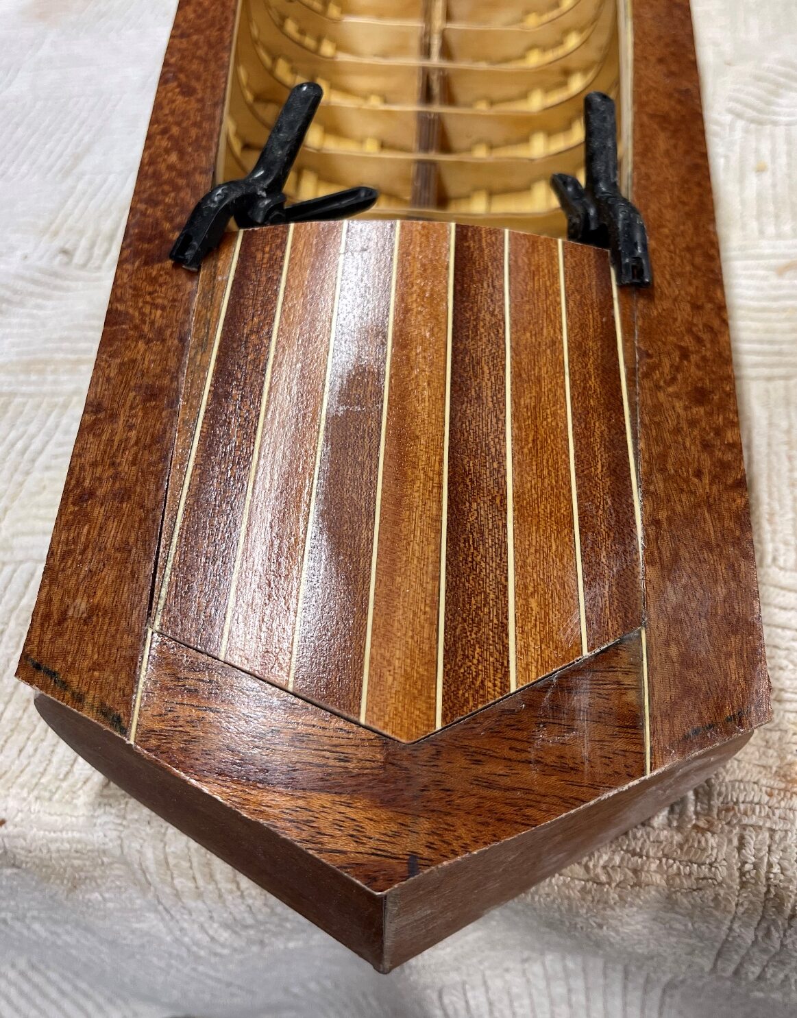
The 3D-printed parts are available as a separate kit. Note, the cutwater is a fairly complex part. A modeller can use the part or can create their own chrome surface on the bow of the model.


A general list of tools you should have on hand:
As with most models, one needs to be very careful with the beginning of the project as early problems tend to get magnified as an assembly progresses.
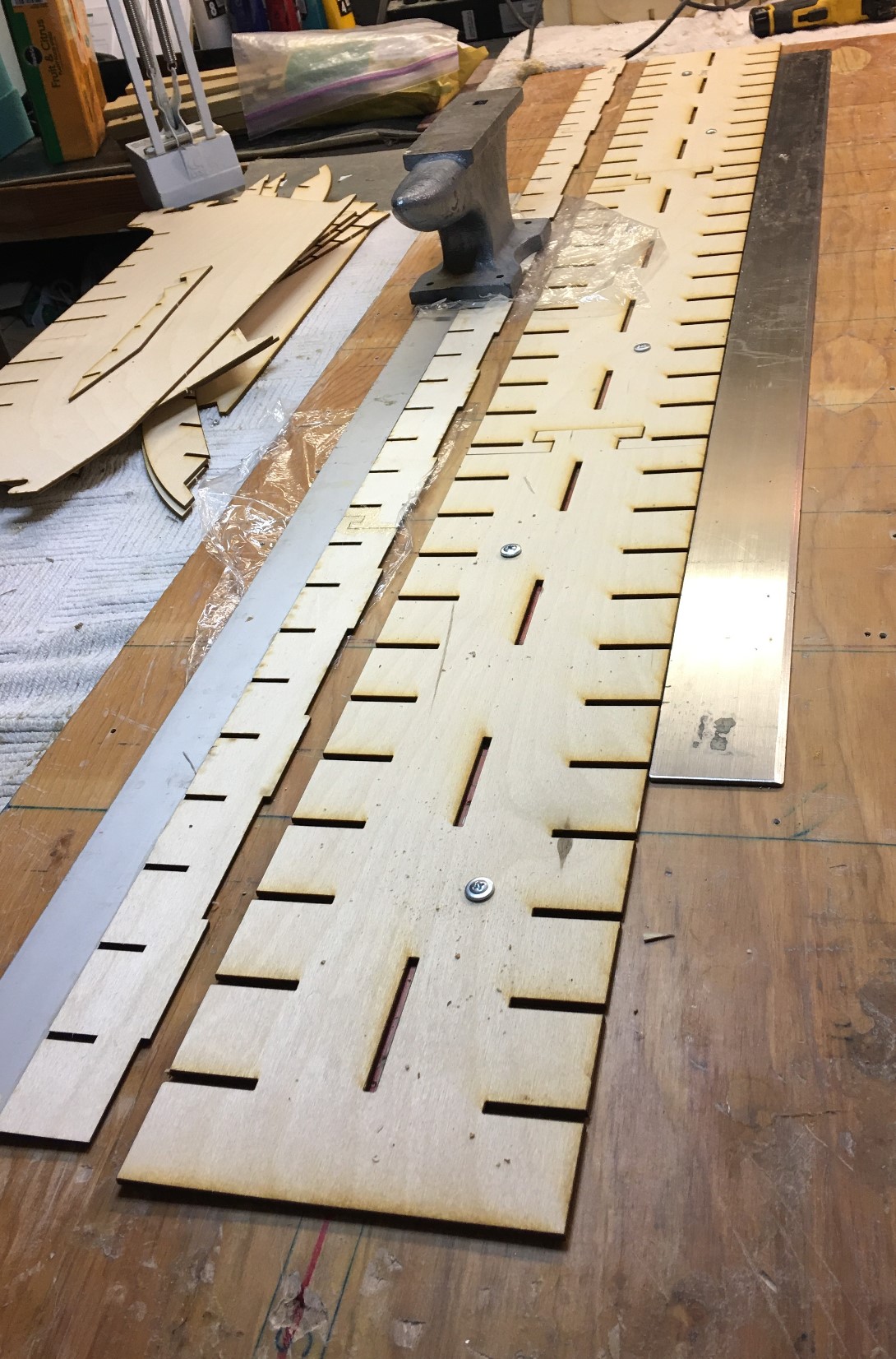
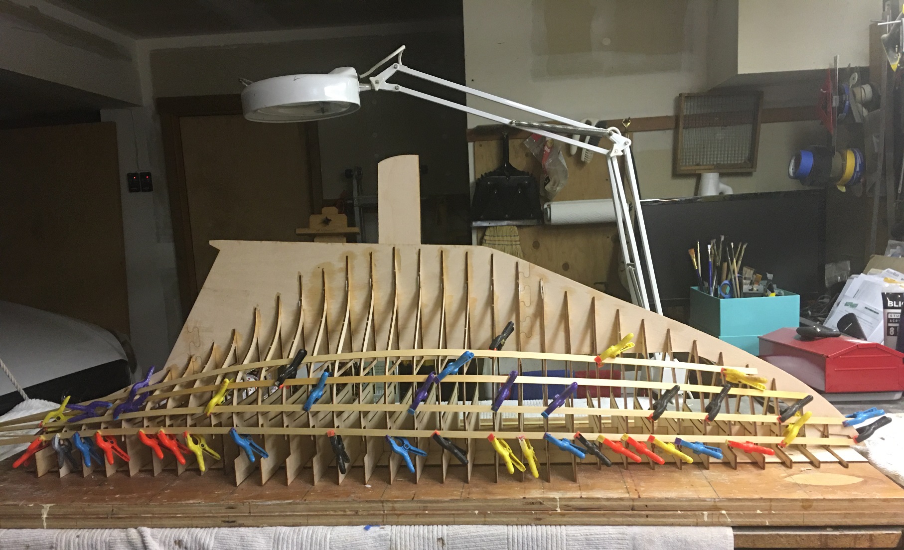
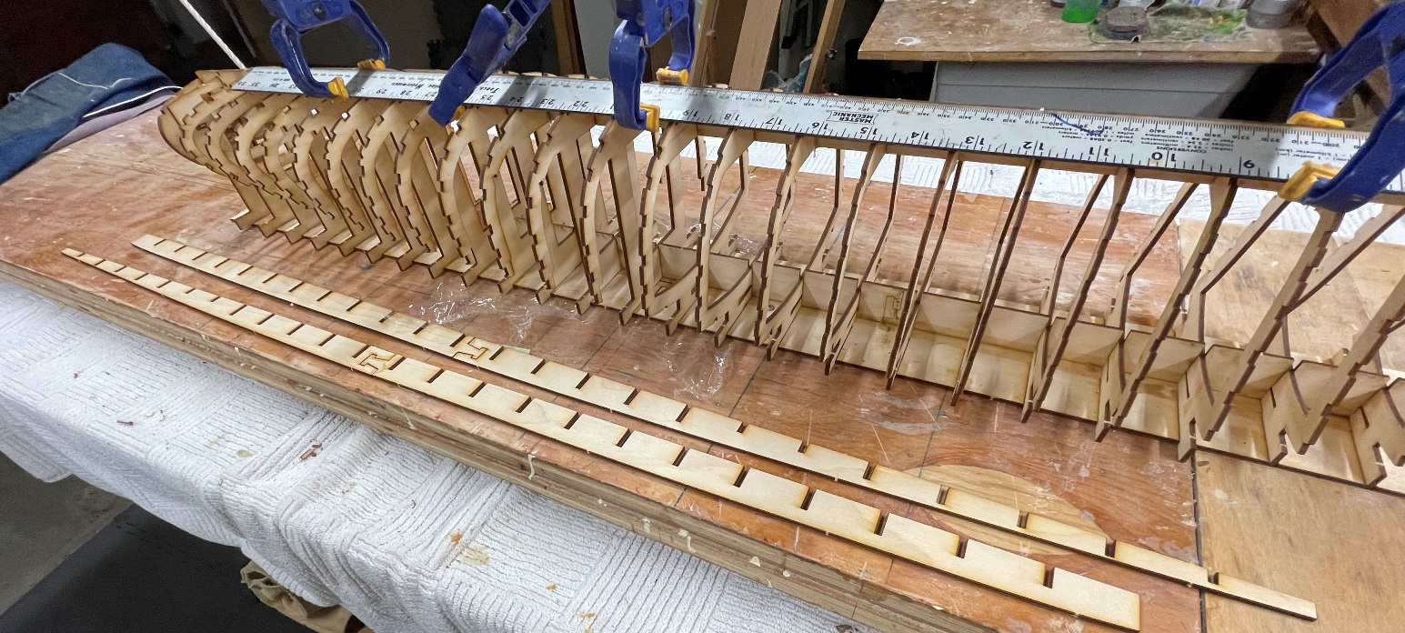
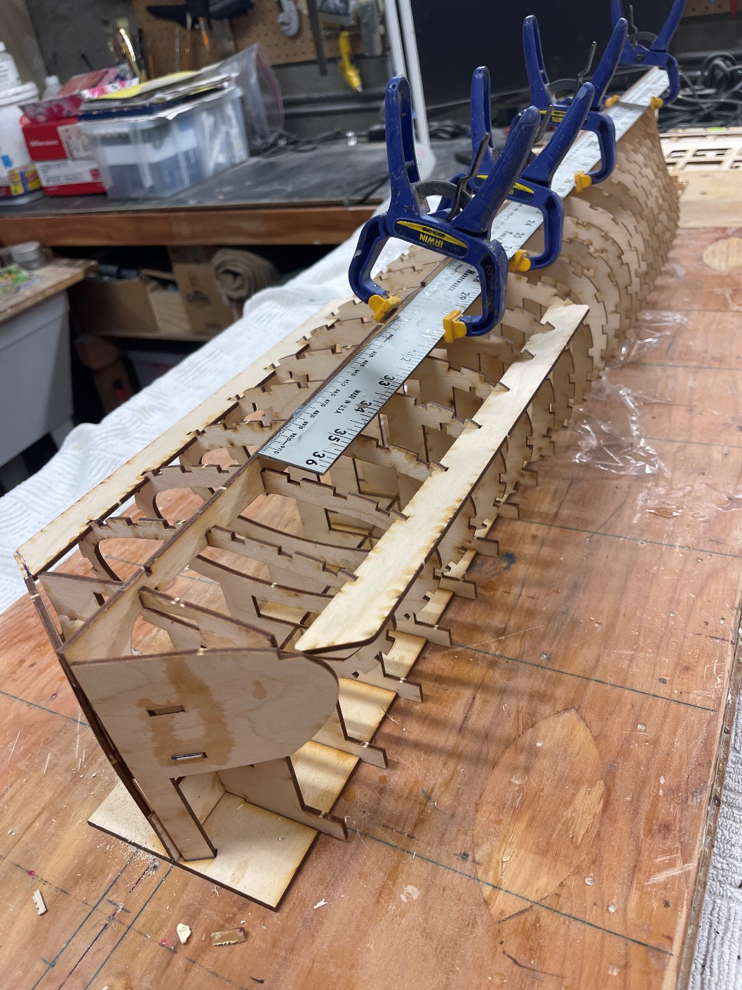
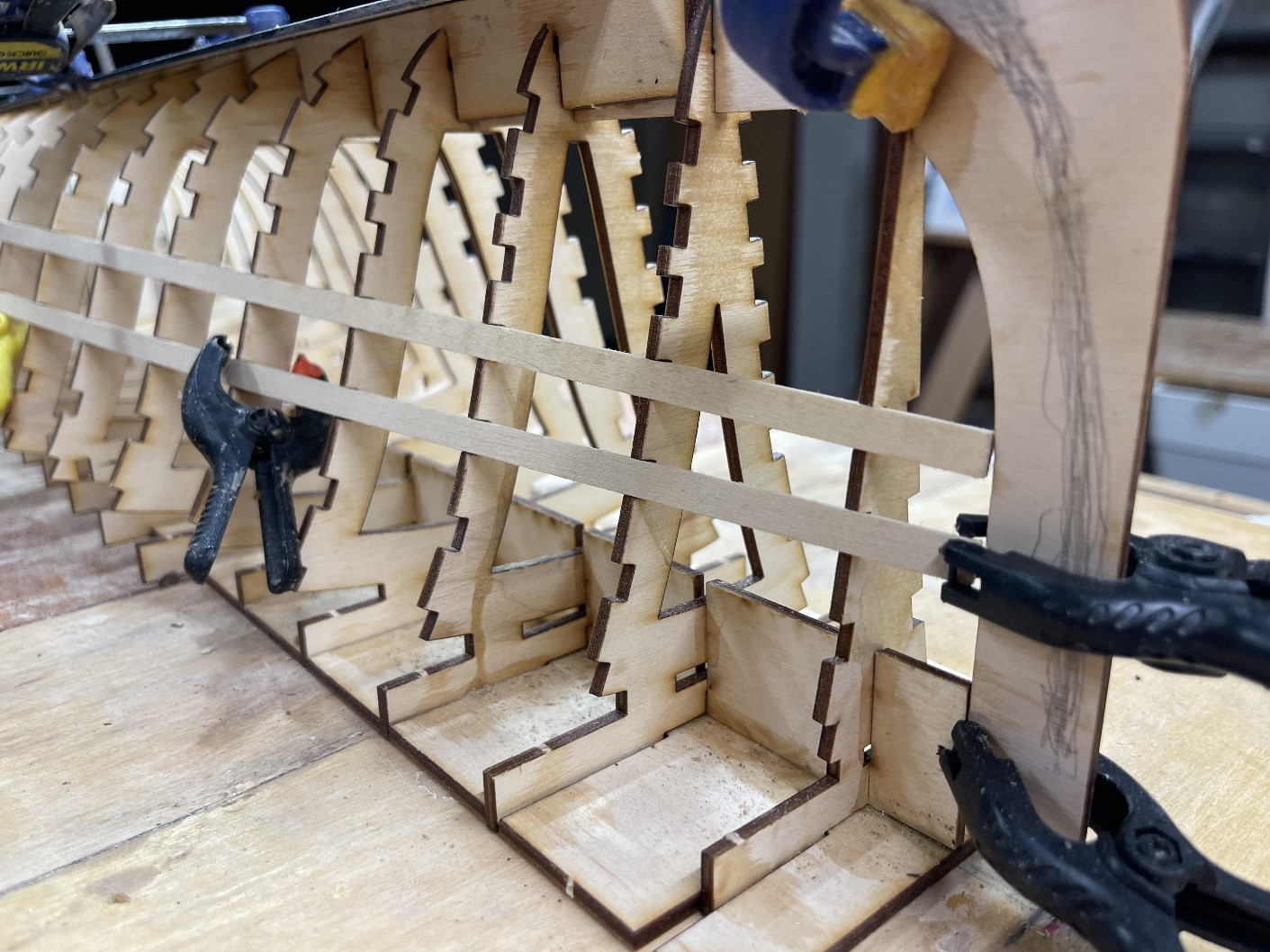
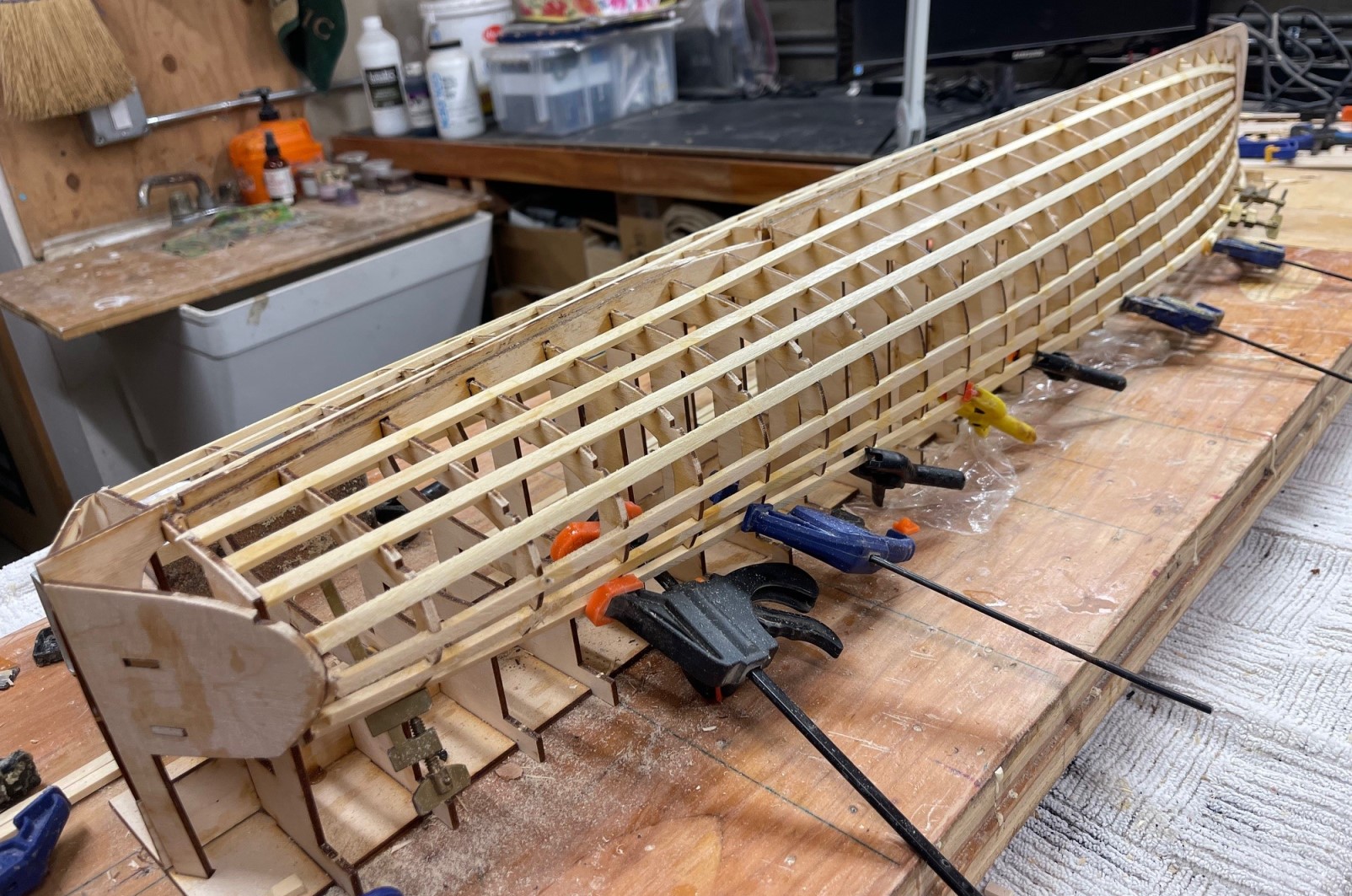
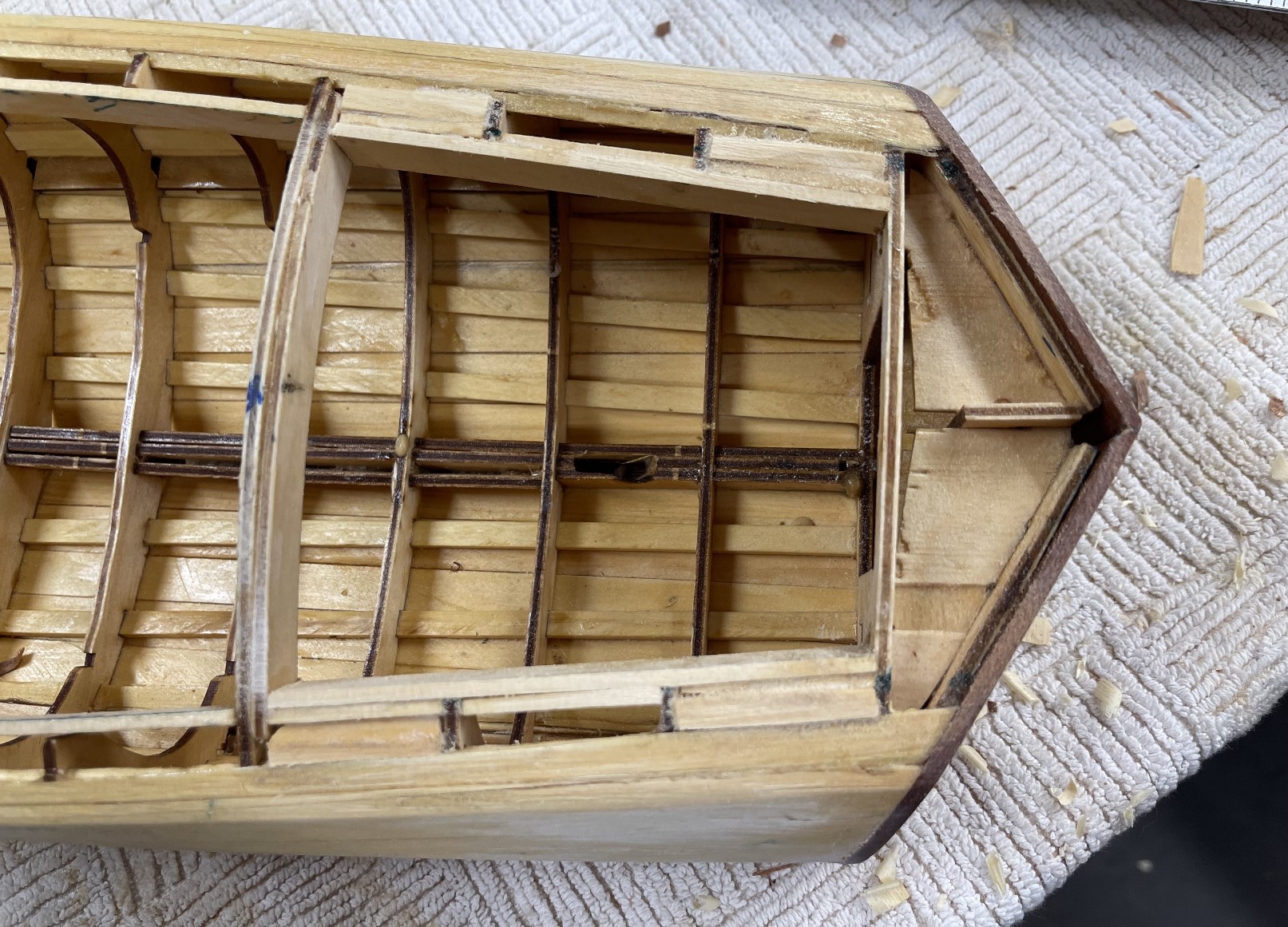
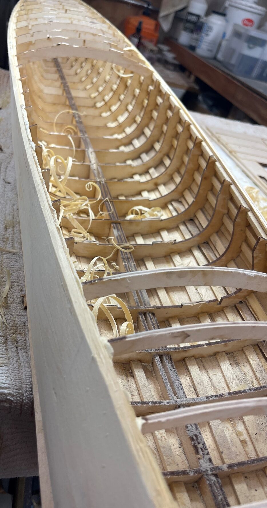
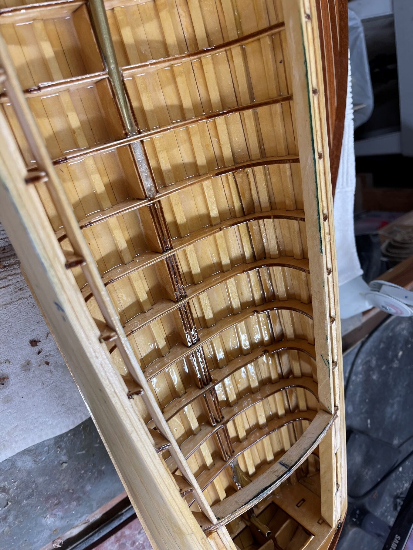
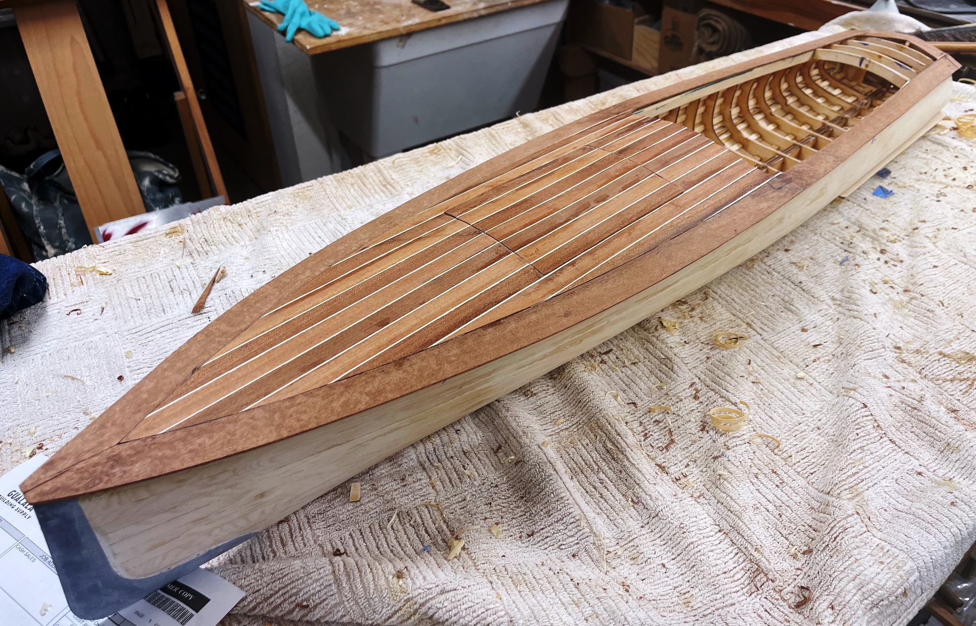
Once the alignment is completed and the keel is installed, it is time to install the stringers. Please note that the stringers are designed as decorative elements of the model. They will look really cool when the model is flipped over. This means it is important to make them look good where they will be visible but the ends themselves are not that important as they will not be seen.
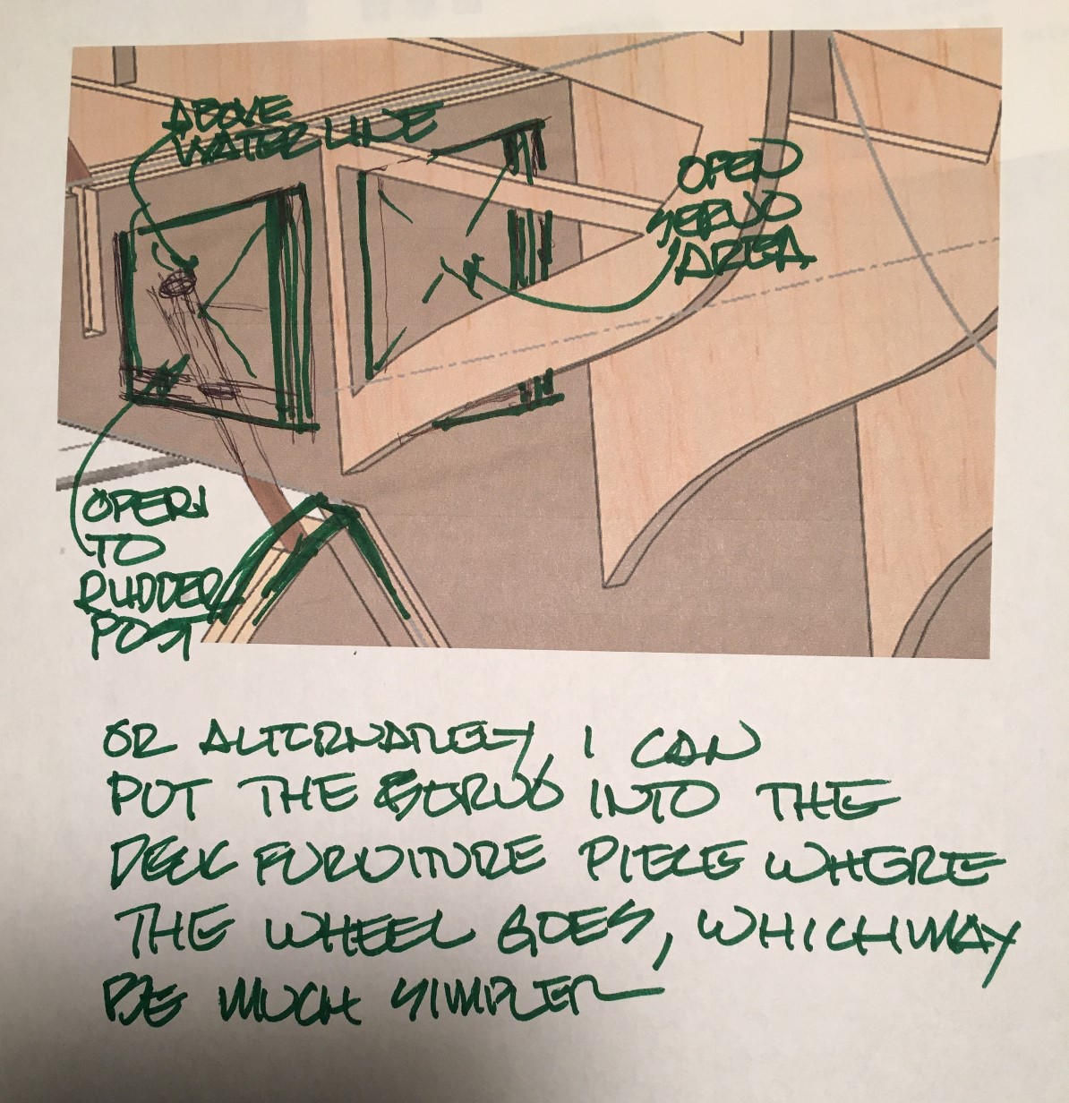
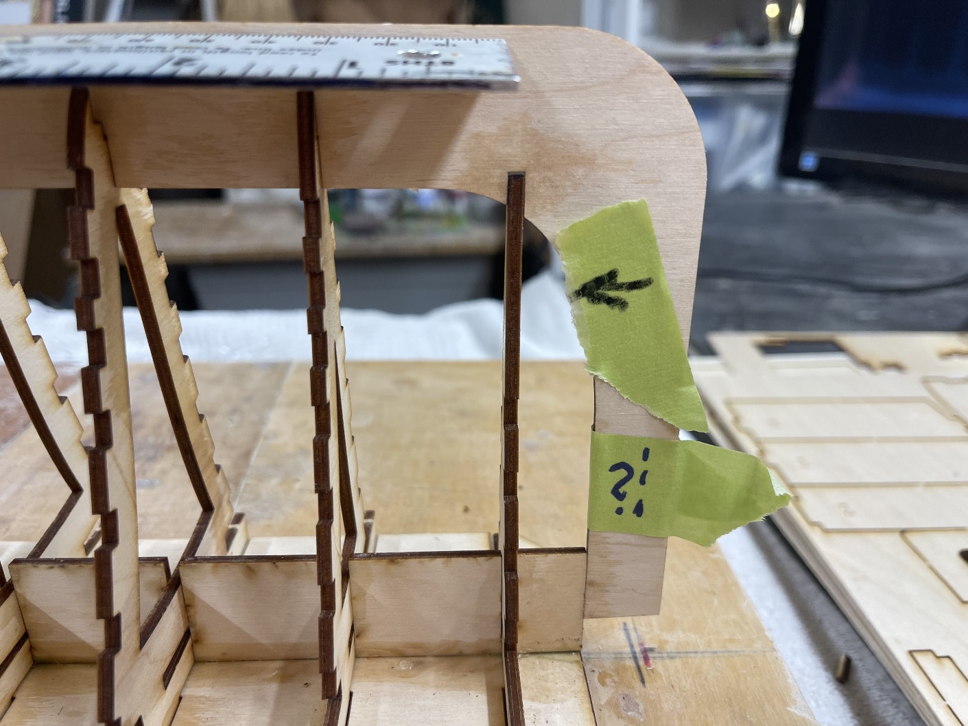
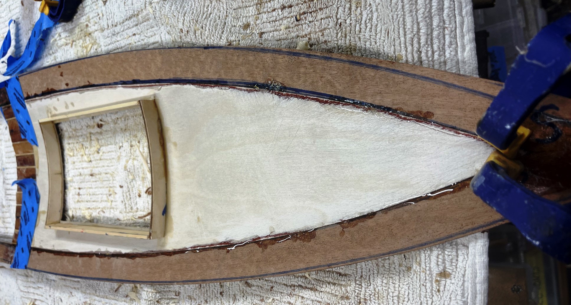
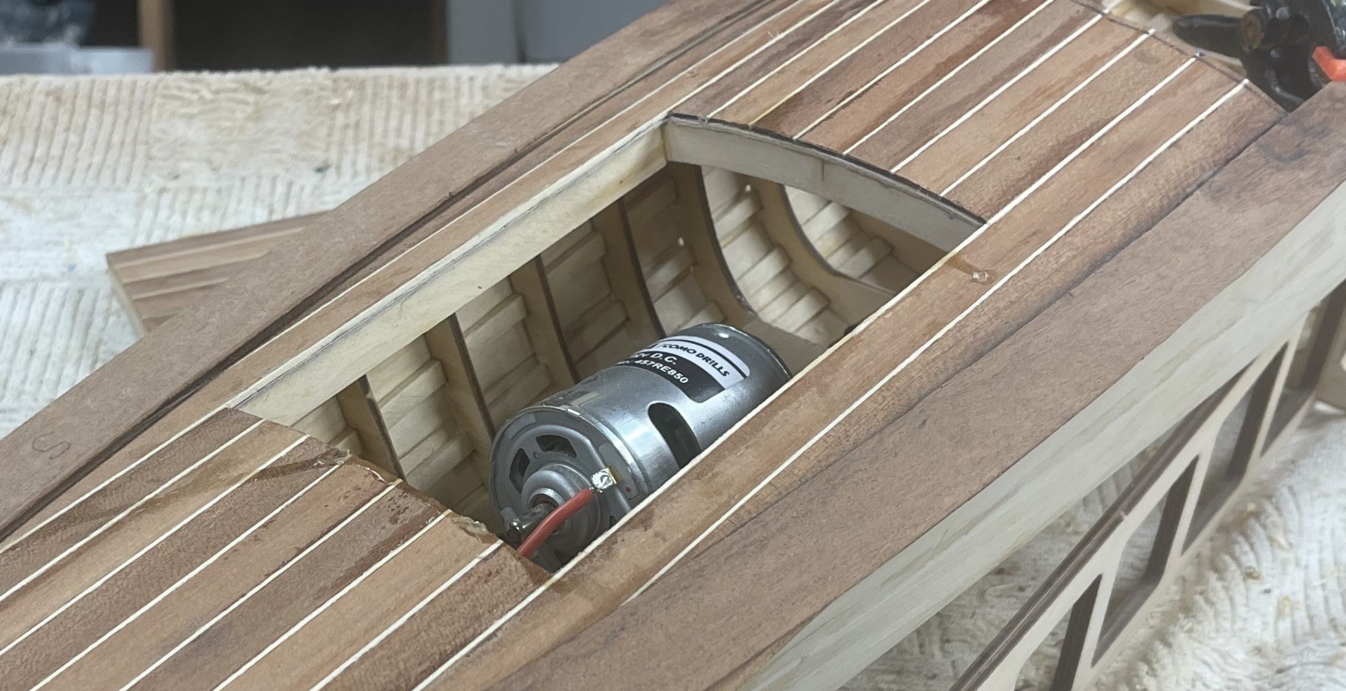
Although the location and slope of the propshaft is noted on the keel pieces, this is no longer easily determined. While the boat is still firmly on the building board, it’s a good time to drill for the prop shaft location. I have learned that the prop shaft should have no more than a 10% angle to the waterline (Needs to be verified)
Again, while the general rudder post location is easily determined, it is critical to verify there will be room within the boat for the rudder arm as well as the rudder servo before drilling the location. Future access to the rudder arm, as well as the servo, is also an important decision at this time.
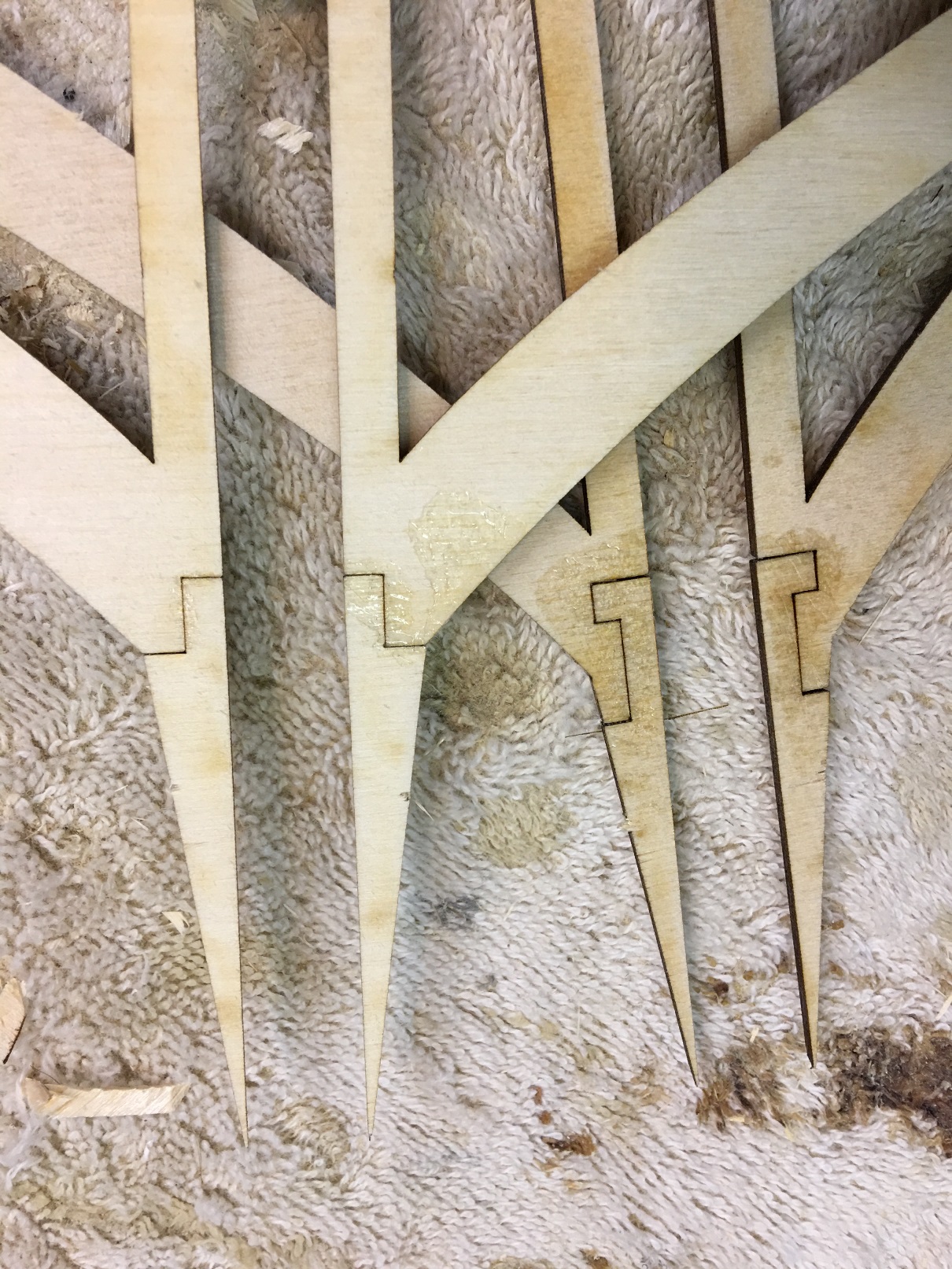
You will notice that there are notches in the last several frames at the stern of the boat for installation of the strakes. These will eventually be parallel to and just at or slightly above the waterline. Usually these are a fragile element of any model, but the notches allow for substantial strength.
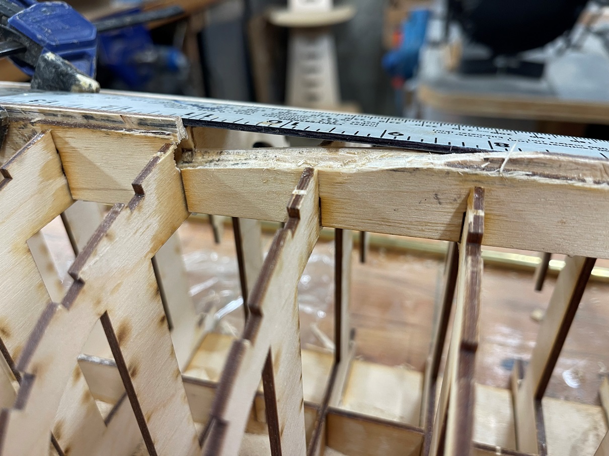
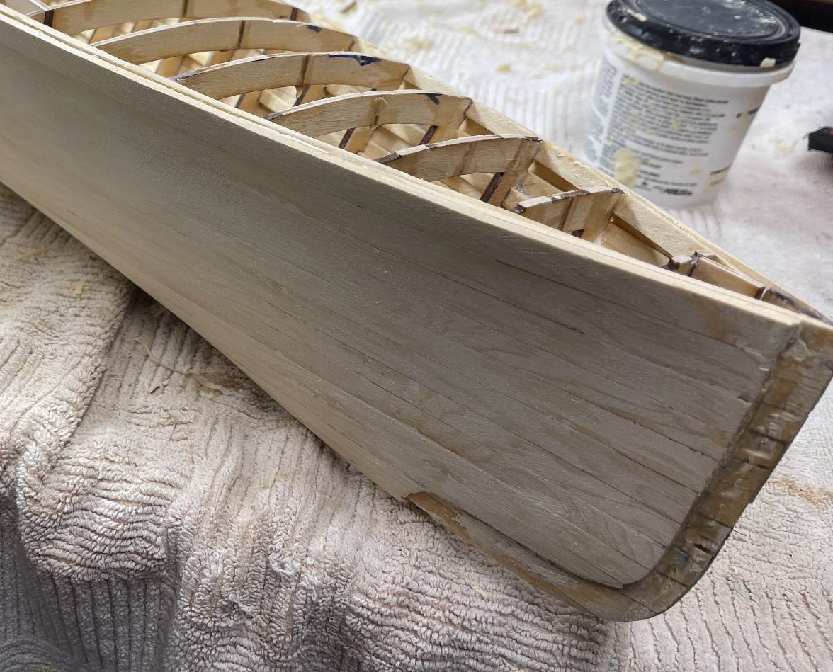
I use two layers of 3/32” x ½” yellow cedar for my boats.
The frame dimensions have taken the thickness of the planking into account.
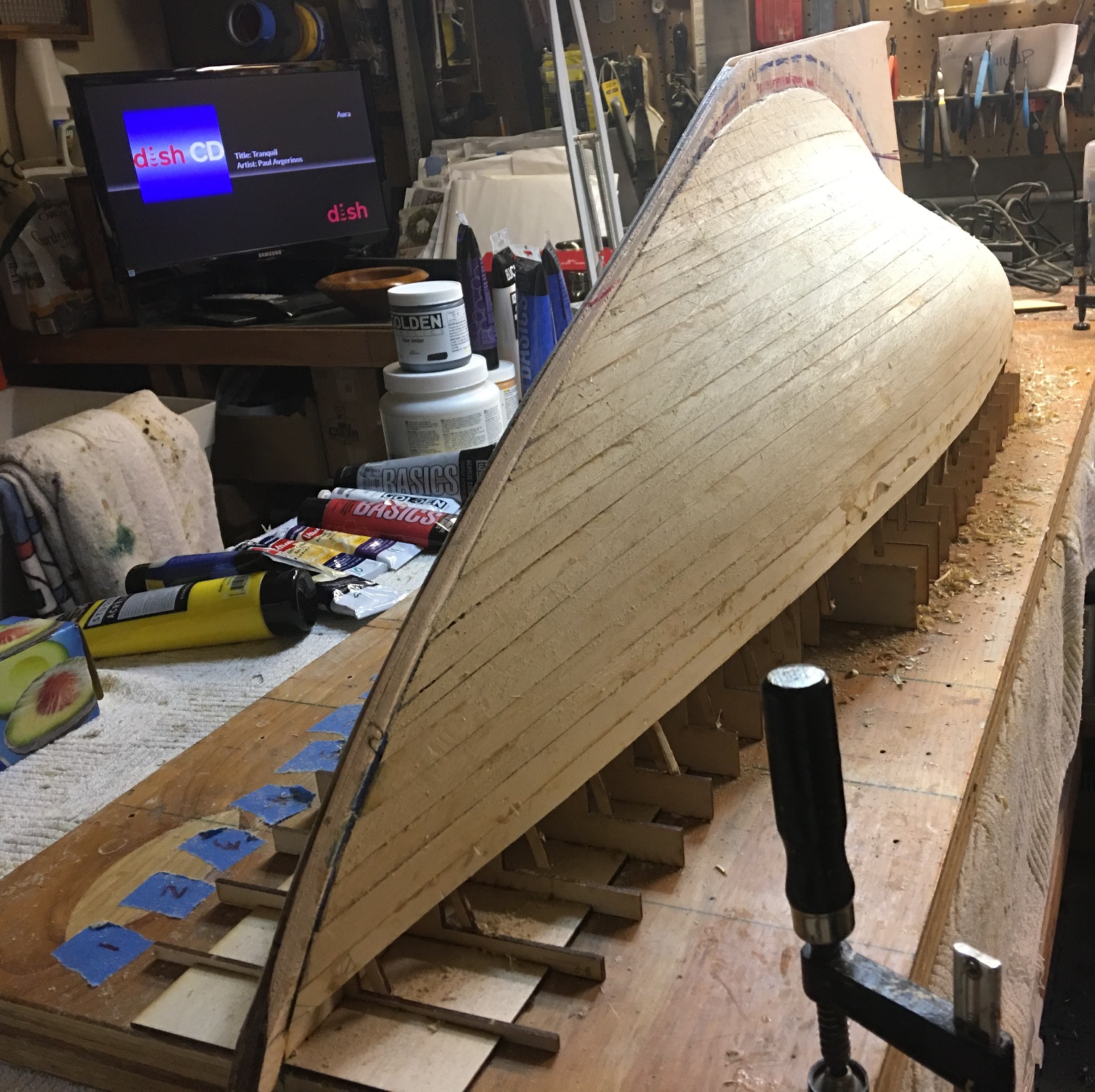
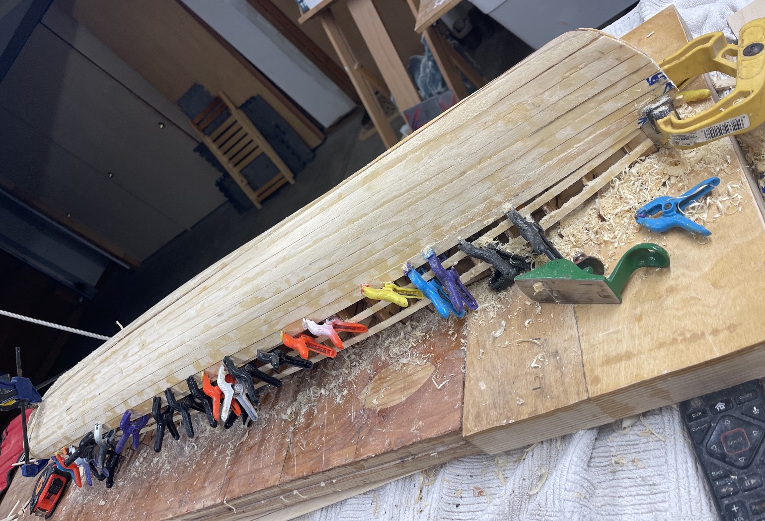
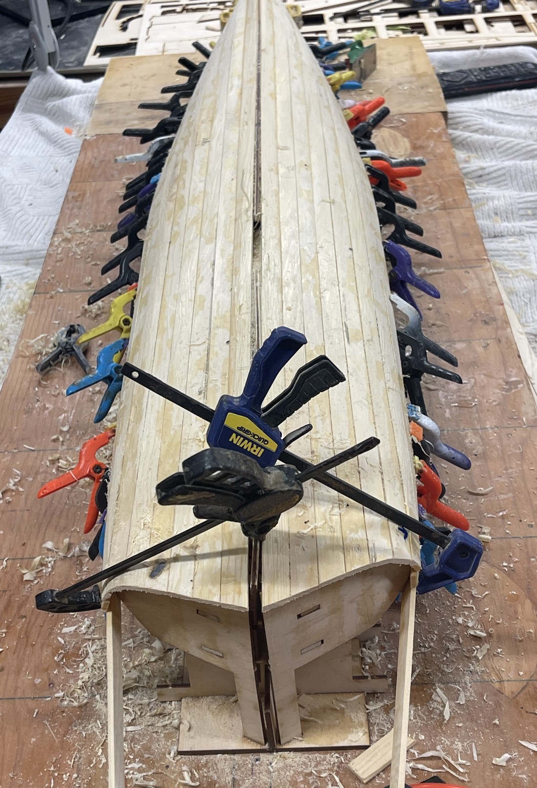
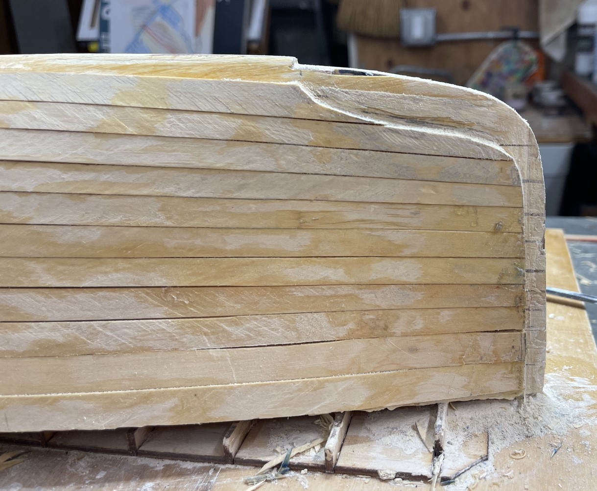
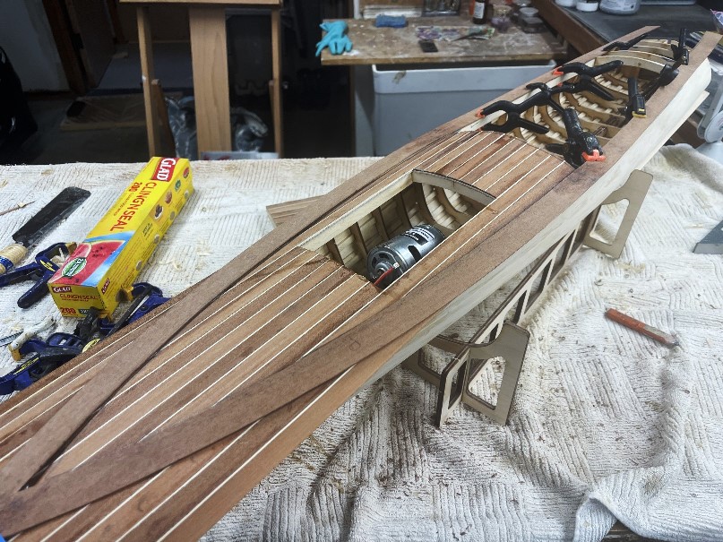
First step is to bevel all the frames so that stringers are just at the surface of each frame. This is simply completed with a sanding block, 120 grit sand paper, some patience, and a light touch. I usually plank the first layer from the keel up to the sheer.
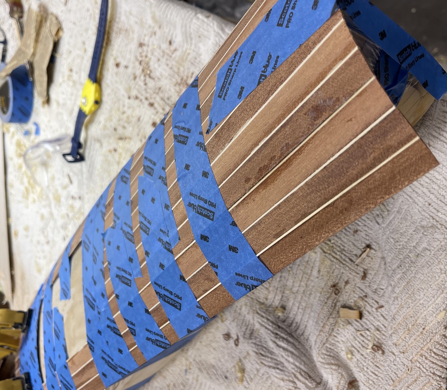
Following completion of this step, which, on the Mower, went remarkably quickly, with virtually no “spiling” of most of the planks, I fair the first layer, using easily sanded wood filler. This insures that the final layer of the hull is very fair with no bumps or depressions. I then add the second layer, planking from the sheer down. I have found that using this sequence removes any chance that seams are aligned.
Locate and roughly clean up the strake locations as you are planking while you can still see them. Strakes will “slot” into these notches after some careful cleaning up and fitting. There are, at this point, two choices.
You may either:
I chose option 1, which, while it took a long time, was a satisfying few hours of
fiddling. And they are strong!
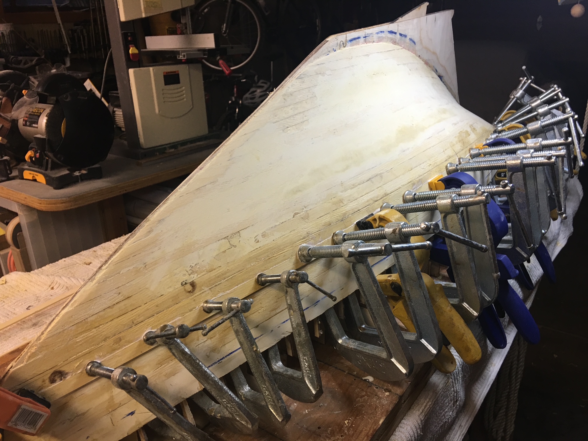
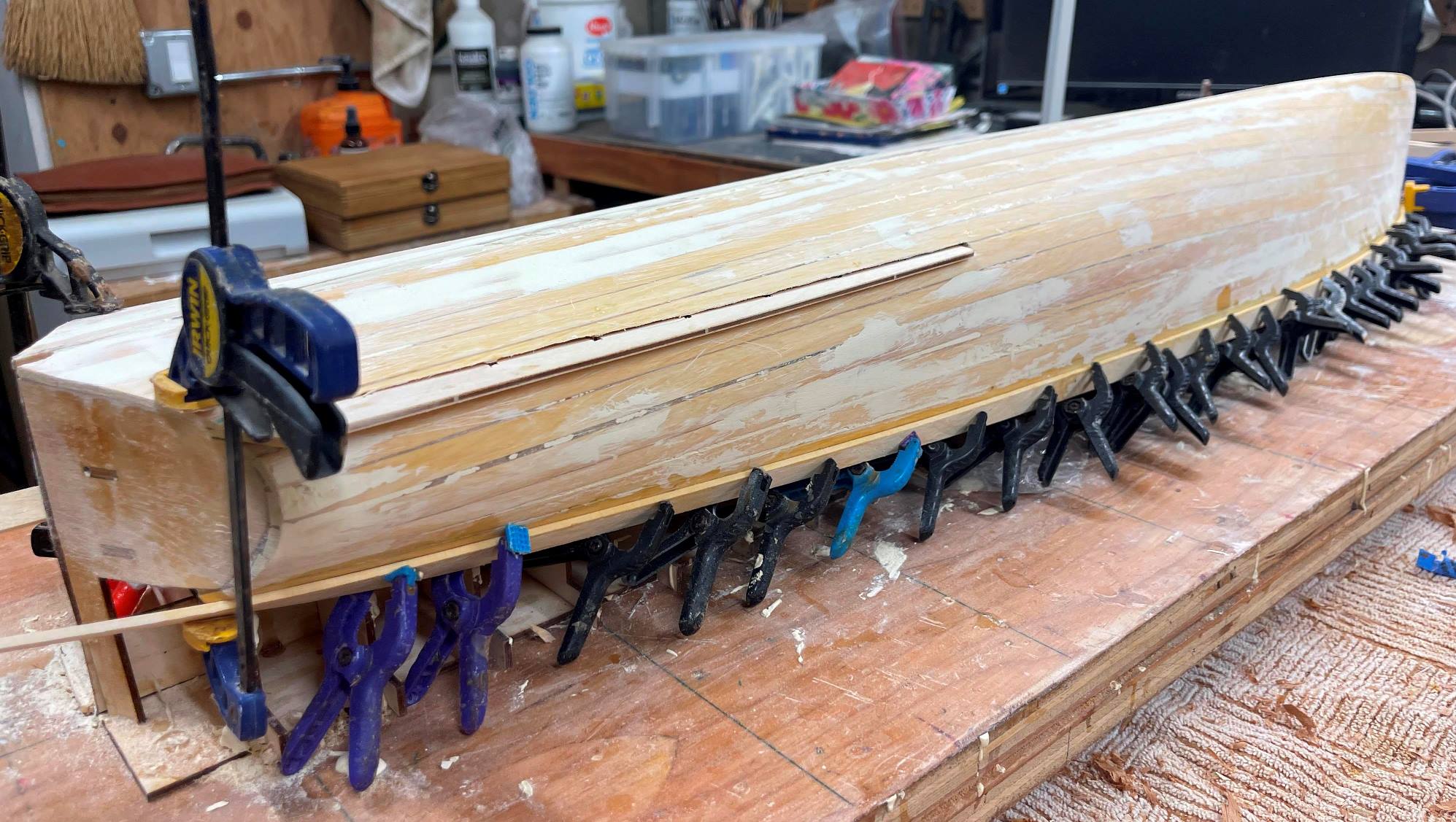
Following completion of the planking, which, on the Mower, went remarkably quickly, with virtually no “spiling” of most of the planks, I fair the first layer, using easily sanded wood filler. This insures that the final layer of the hull is very fair with no bumps or depressions. I then add the second layer, planking from the approximate sheer down. I have found that using this sequence removes any chance that seams are aligned. Locate final strake location and fit strakes permanently.
Re drill prop shaft location.
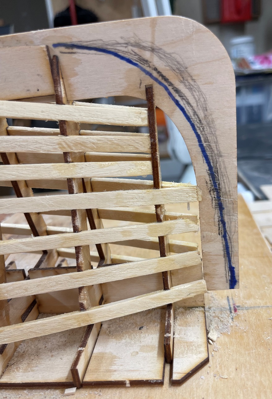
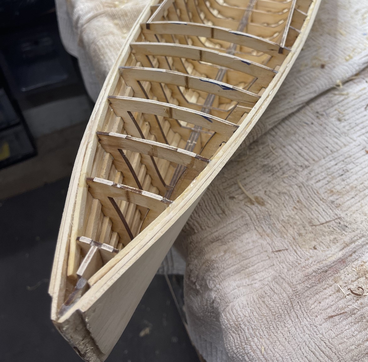
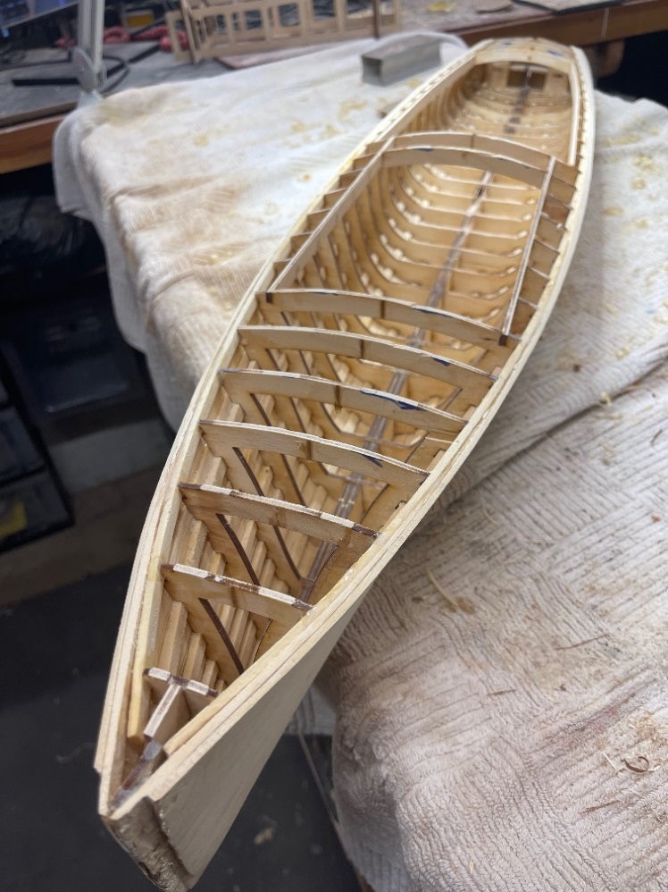
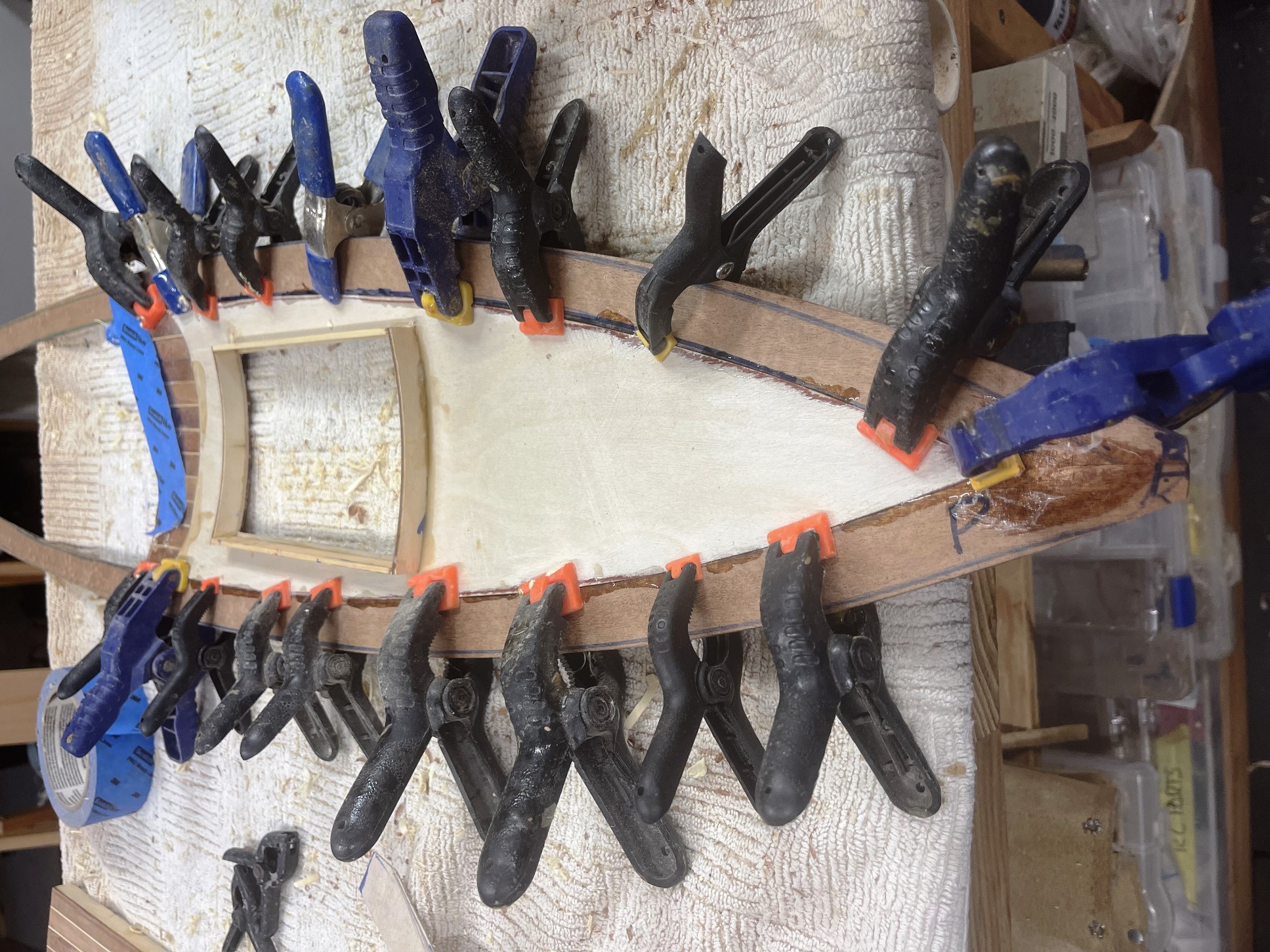
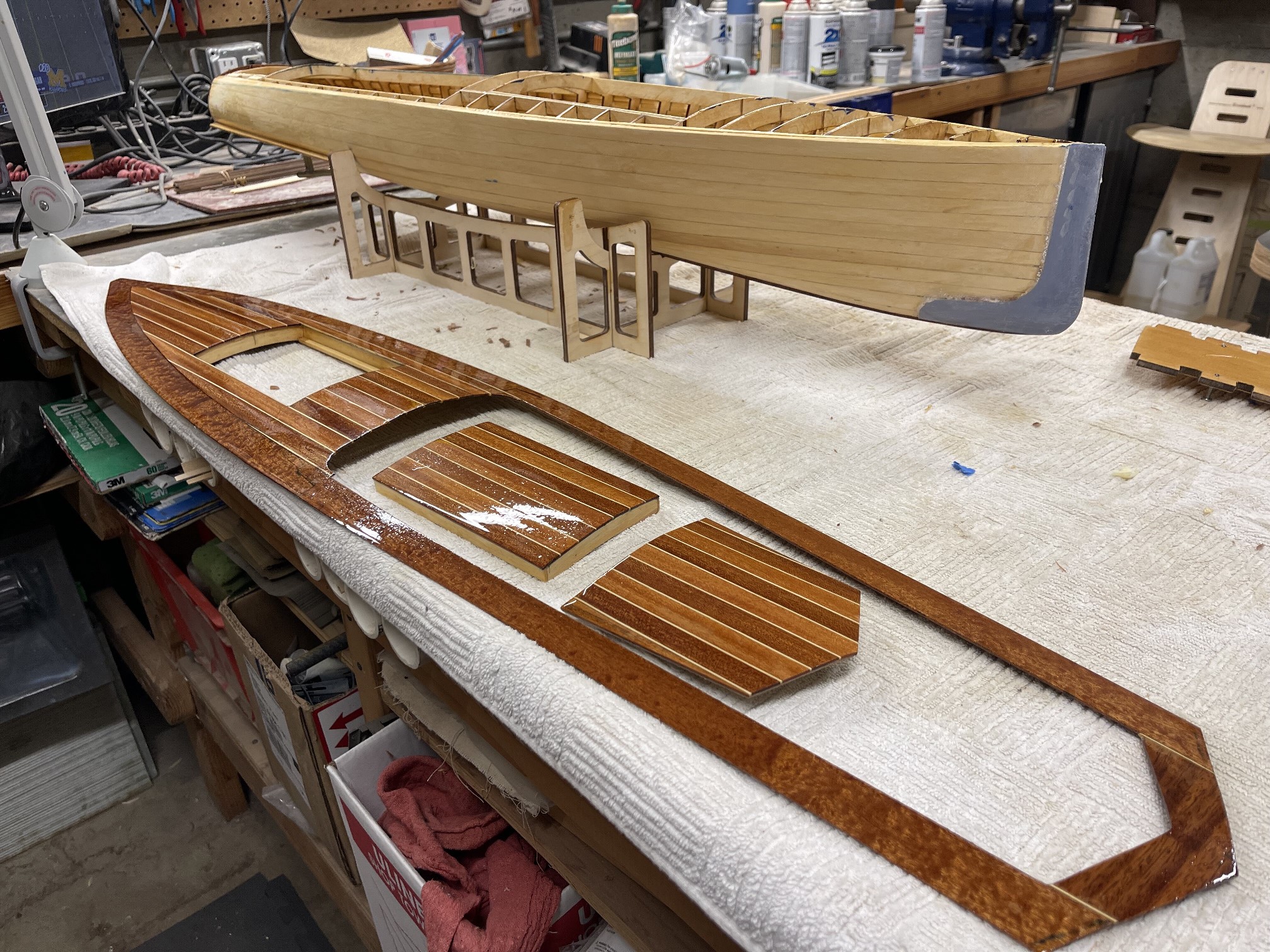
Its time to release th hull from it’s foundation. While, with care. This is easily accomplished (I use a Japanese saw) , it is also too easy to let the saw wander and start cutting into the carefully built hull. To this, I say, take your time, and verify each cut. There is a lot of excess wood, and it
can be confusing what to cut, and what is your precious hull. Remember, you will be cleaning up the frames and the interior after the boat is released from the building board, and access for final trimming will be much easier. Final trimming of the frames at the deck level will also establish the sheer line of
the boat, so constant use of a batten strip to carefully establish the sheer is
critical.
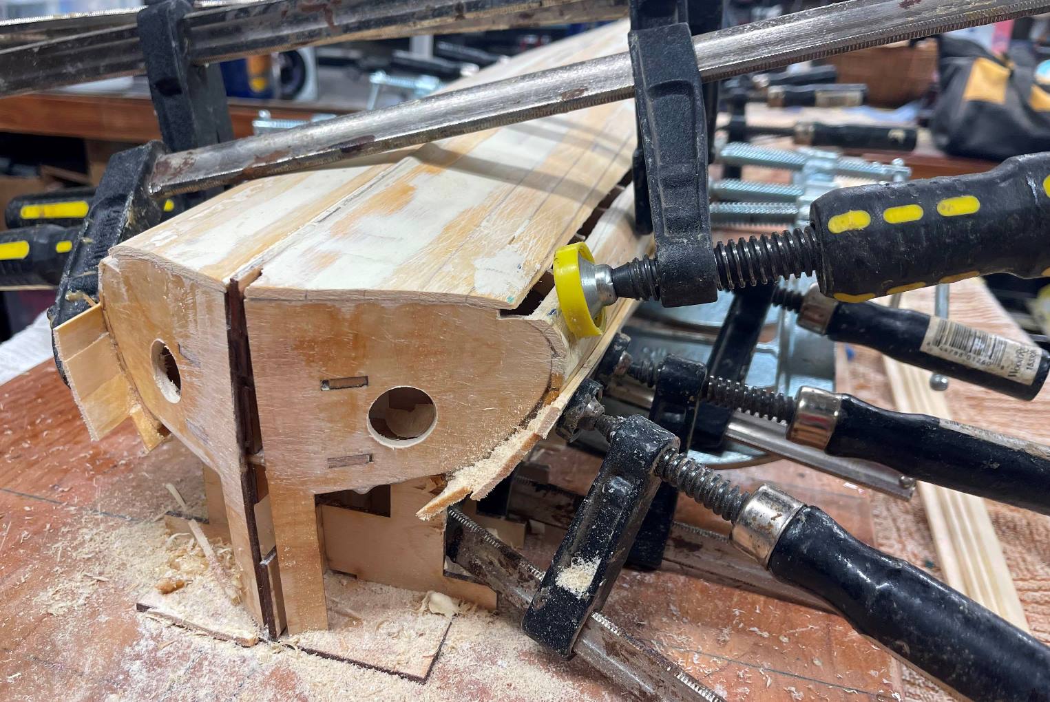
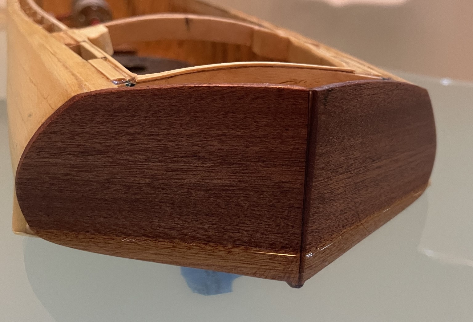
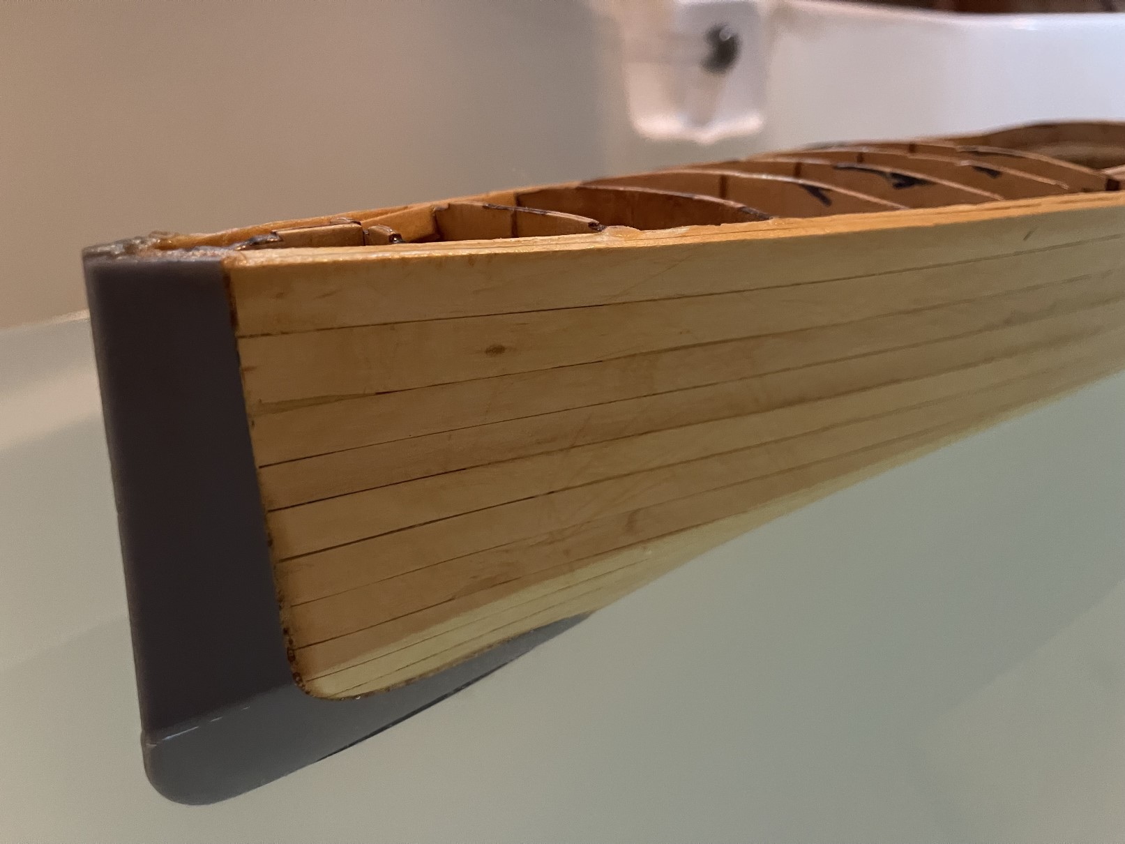
I chose to fit the 3D printed cutwater after planking, although a case can be made
to fit it to the hiull before any planking or after the first layer of planks. Under any
circumstance, the cutwater fits flush with the hull..
As with most models,

Yup, that's me in front of the Gaspé, in Quebec