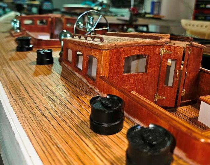


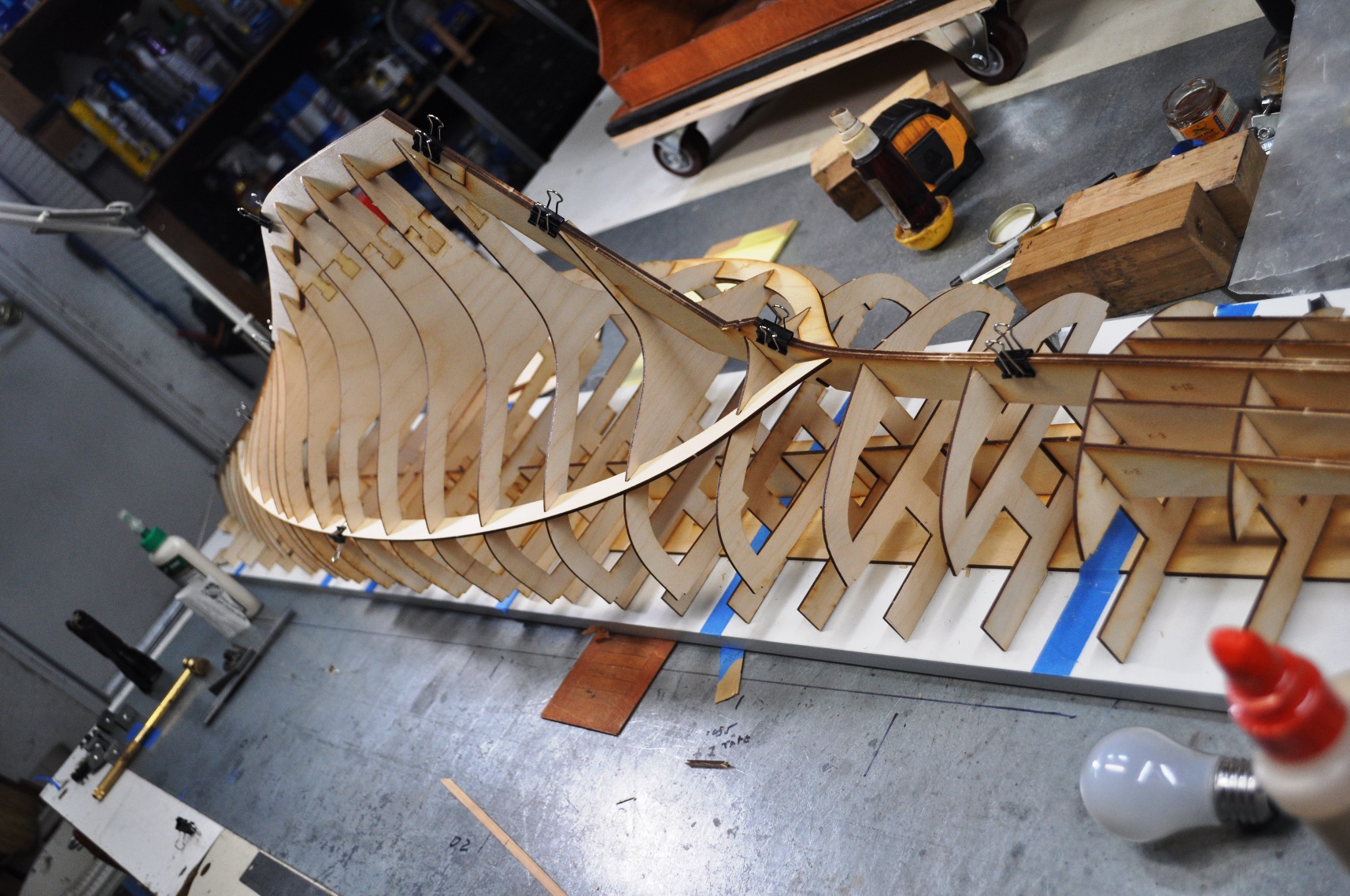


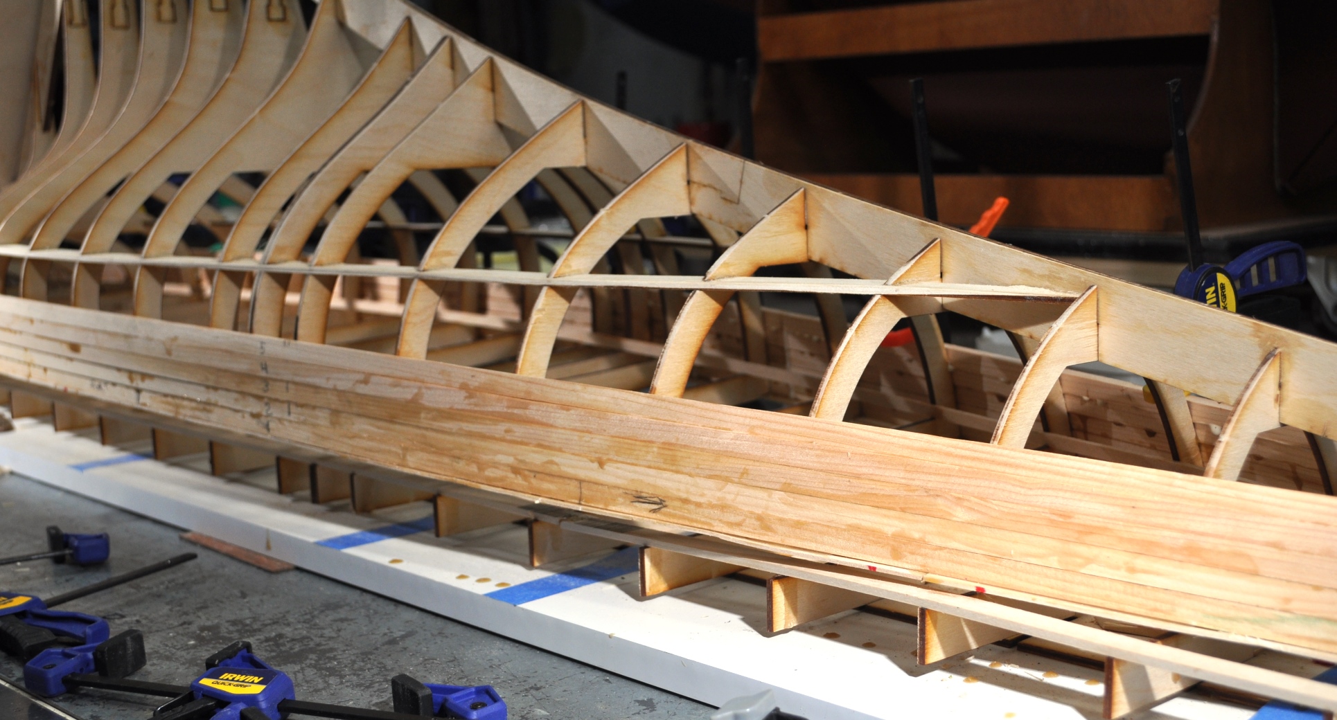
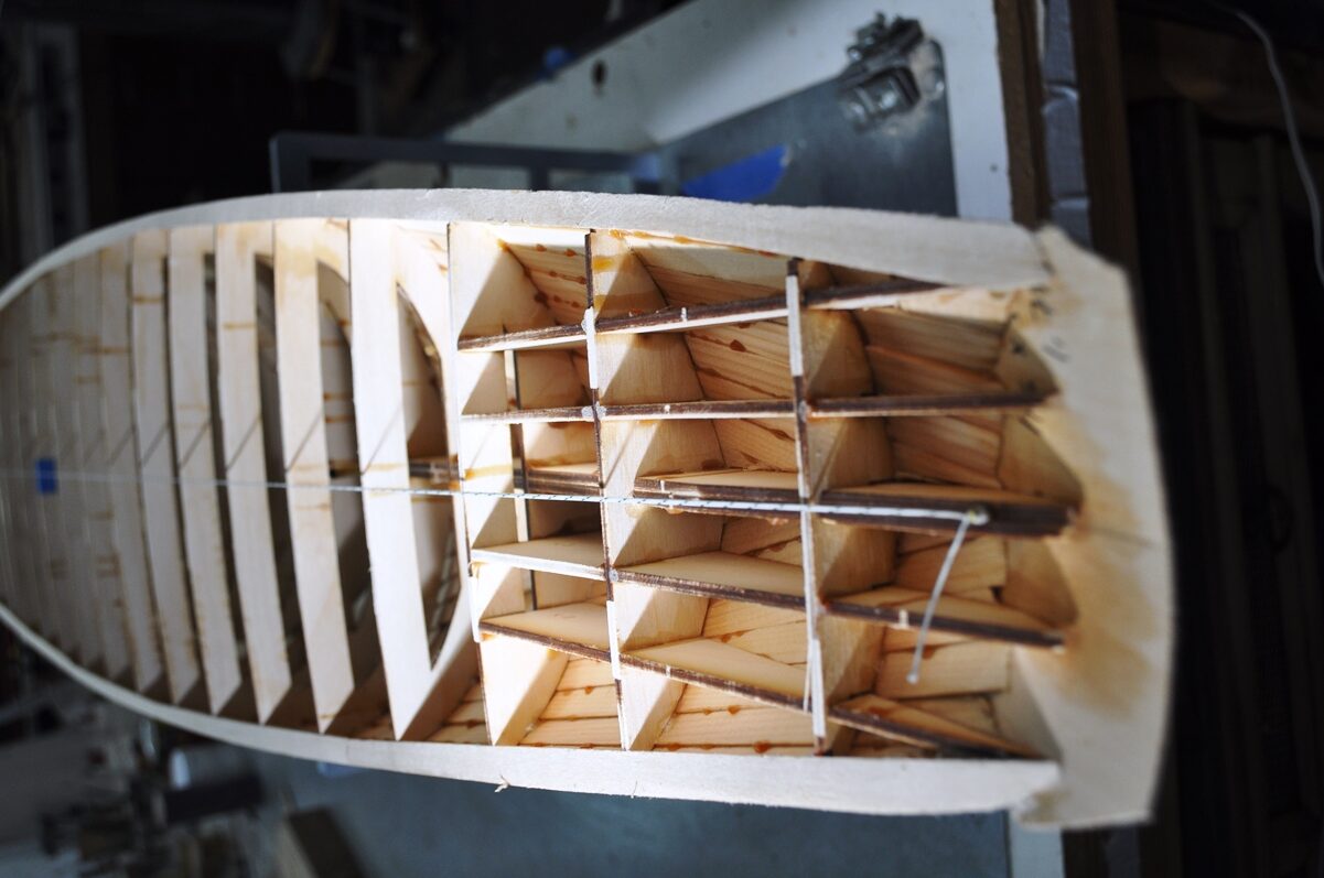
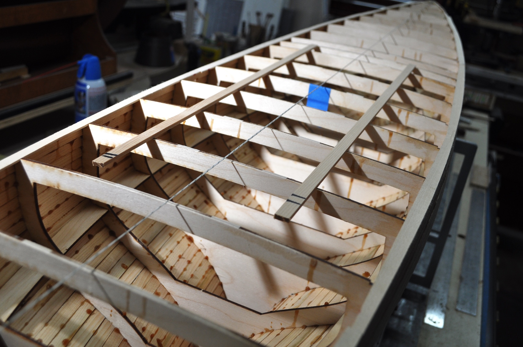

George Crouch’s Baby Bootlegger From Wikipedia: “Baby Bootlegger is an American wooden-built speedboat. It was designed by George Crouch for Caleb Bragg in early 1924, and
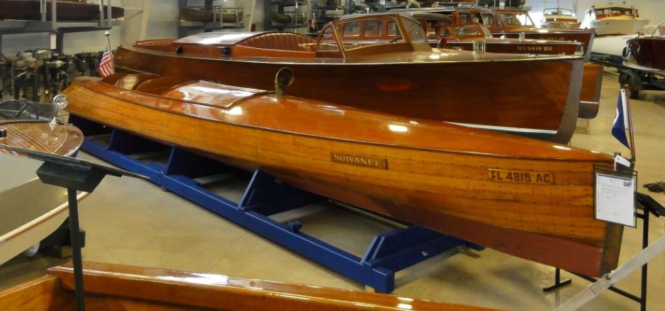
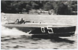
L.E. Fry’s 1909 Suwanee The original boat is in the Antique Boat Museum, in Clayton, New York. From the museum’s